
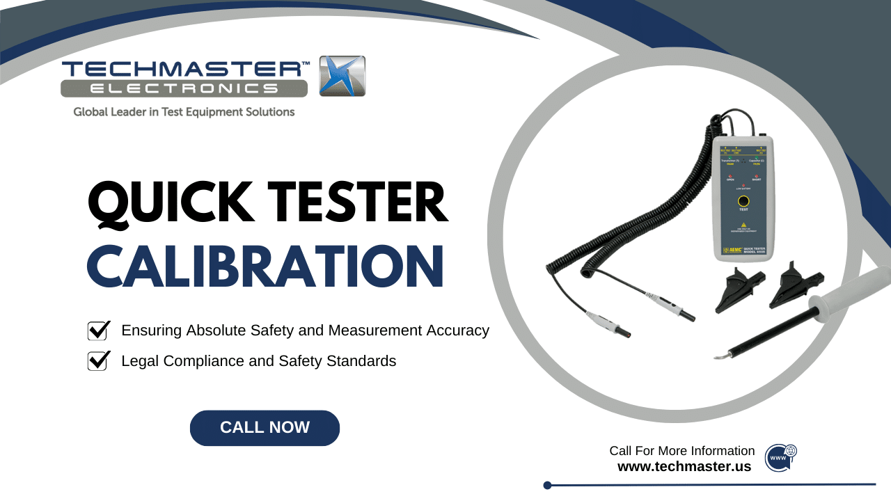
QUICK TESTER Calibration
Accuracy across the range
How QUICK TESTER calibration works
- Intake & visual inspection
- Environmental stabilization
- As-found measurement
- Comparison to NIST-traceable standards
- Adjustment if required
- As-left results & certificate
Your calibration, covered
In-lab vs on-site calibration
In-lab calibration
- Accredited bench with full reference standards
- Best achievable measurement uncertainties
- Pickup & return logistics handled
- Ideal for precision and reference work
On-site calibration
- We calibrate the QUICK TESTER at your facility
- No shipping risk or transit downtime
- As-found data captured before any move
- Ideal for fixed, large or sensitive assets
In-depth guide
Quick Electrical Tester: Ensuring Absolute Safety & Electrical System Integrity – The Importance of Calibration
In the electrical and industrial maintenance fields, checking parameters like voltage, current, and continuity is a daily requirement. Errors in electrical measurement not only endanger the lives of electricians but also lead to equipment damage, fire hazards, and serious operational downtime. The Quick Electrical Tester is an essential tool. It provides rapid, precise measurement of multiple electrical parameters in a single device. This instrument helps technicians quickly identify voltage issues, check circuit continuity, and verify phase rotation in three-phase systems. Nevertheless, voltage and current sensors are susceptible to drift due to factors such as overload, temperature fluctuations, or physical impact. Therefore, routine QUICK TESTER Calibration is a mandatory requirement. Through calibration, the device’s accuracy is verified, ensuring that every safety measurement and fault diagnosis remains reliable and trustworthy.
1. What is a Quick Electrical Tester?
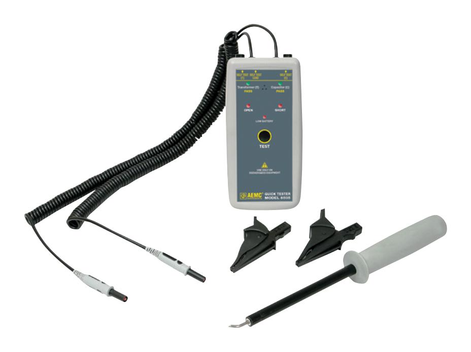
A Quick Electrical Tester is a compact handheld diagnostic tool designed for fast verification of essential electrical parameters. With its simple operation, technicians can instantly check voltage presence, continuity, polarity, and other basic circuit conditions. Moreover, by providing rapid and reliable readings, the tester helps ensure electrical safety and prevents accidental exposure to live circuits. As a result, it supports accurate assessment of a system’s operational status before maintenance or troubleshooting begins.
1.1. Objective and Key Measurement Parameters
-
Objective: To rapidly test the electrical status, verify the presence of hazardous voltage, and check the integrity of a circuit.
-
Key Measurement Parameters:
-
AC/DC Voltage: Measures the current voltage level in the circuit.
-
Continuity: Checks whether the electrical circuit is open or short-circuited.
-
Phase Rotation: Verifies the correct phase sequence in three-phase systems (crucial for motors and pumps).
-
1.2. Basic Operating Principle
2. Vital Applications in Electrical Installation and Maintenance
A multifunction electrical tester helps technicians quickly verify essential electrical conditions for safety and system operation.
Measurement Importance
- ■ Voltage verification (40%)
- ■ Phase rotation (30%)
- ■ Continuity (20%)
- ■ Other measurements (10%)
Critical Applications
- ⚡ Energy isolation verification: ensuring zero voltage before maintenance.
- 🔁 Phase rotation testing: prevents motor damage due to incorrect wiring.
- 🌍 Ground continuity testing: ensures proper grounding to prevent electric shock.
The accurate measurement capability of this device is the foundation for safety and operational efficiency.
2.1. Ensuring Electrical Safety
-
Zero Voltage Verification: This is the most crucial application. Before performing any maintenance work, technicians must use this device to verify the absence of voltage (Zero Voltage Verification) at the working point, ensuring absolute safety.
-
Grounding System Checks: Checking the continuity of the grounding system is mandatory to protect people and equipment from electrical shock.
2.2. Motor and Three-Phase System Installation
-
Phase Sequence Check: Installing a three-phase motor with the wrong phase sequence (phase reversal) can damage the motor immediately. This device helps verify the correct phase rotation before startup.
-
Rapid Fault Diagnosis: It helps technicians quickly determine whether a fault is due to voltage loss, a short circuit, or a phase issue.
2.3. Residential and Industrial System Testing
-
Outlet and Appliance Testing: Ensures that the voltage supplied to outlets and appliances remains within permissible limits.
3. The Absolute Role of QUICK TESTER Calibration
Voltage sensing components can drift over time, causing a false “0V” reading—a life‑threatening hazard.
Life‑Threatening Hazard
A false 0V reading may cause a technician to touch an energized circuit → risk of fatal shock.
Incorrect Diagnostics
A 10% error can cause unnecessary component replacement, increased downtime, and cost.
An inaccurate electrical measurement can pose a threat to life or lead to incorrect fault diagnosis, making Quick Electrical Tester Calibration paramount.
3.1. Ensuring Absolute Safety and Measurement Accuracy
-
Risk of Drift: The device’s voltage sensors can drift after overload, particularly when exposed to sudden voltage transients. As this drift increases, the tester may incorrectly indicate zero voltage even when hazardous voltage is still present. Consequently, this creates a severe—and potentially fatal—electric shock risk for anyone relying on the faulty reading.
-
Value Verification: QUICK TESTER Calibration verifies that the device accurately measures voltage, current, and continuity against reference electrical standards.
-
Preventing Misdiagnosis: Inaccurate data leads to replacing the wrong components, causing wasted time and cost.
3.2. Legal Compliance and Safety Standards
-
Standard Requirements: Labor safety standards and electrical industry regulations mandate that electrical testing equipment must be calibrated periodically.
-
Safety Audit Evidence: The Calibration Certificate serves as formal proof that the organization is taking comprehensive measures to ensure employee safety. Moreover, this documentation becomes especially important during safety audits or accident investigations, where verified measurement accuracy demonstrates due diligence and regulatory compliance.
4. Quick Electrical Tester Calibration Process
Calibration compares the instrument against traceable electrical standards.
High‑accuracy voltage/current calibrators.
Voltage, continuity, phase, and more.
Fine‑tuning or applying correction factors.
Provides safety and compliance evidence.
The QUICK TESTER Calibration procedure is performed in a controlled environment:
-
Reference Standards: We use high-accuracy, traceable, and calibrated reference voltage/current standards (e.g., Calibrators).
-
Check and Compare: The technician applies known levels of voltage, current, and simulates continuity status. They compare the reading on the Electrical Tester with the precise value from the reference standard across various ranges.
-
Adjustment and Confirmation: If a deviation occurs, the device is adjusted (if possible) or a correction factor is recorded. The phase rotation function is also checked by simulating three-phase signals.
-
Certification: A Calibration Certificate is issued, confirming the device’s accuracy and the next calibration due date.
Conclusion
Frequently asked questions
What is QUICK TESTER Calibration?
How often should a QUICK TESTER be calibrated?
What standards apply to QUICK TESTER Calibration?
What is included on the certificate?
Can you calibrate the QUICK TESTER on-site?
Need QUICK TESTER calibration?
ANAB-accredited, NIST-traceable, fast turnaround — in-lab or on-site across the USA.
Contact us for a quoteReferences & industry standards
- ISO/IEC 17025 testing & calibration laboratory requirements
- NIST calibration services and measurement traceability
- NIST Fundamental Electrical Measurements
- A2LA / ANAB accreditation for calibration laboratories
External standards bodies. Techmaster Electronics is an ISO/IEC 17025-accredited, NIST-traceable calibration laboratory.

Khanh Nguyen is the Marketing Manager at Techmaster Electronics, a B2B marketing leader covering the test & measurement and ISO/IEC 17025 accredited calibration industry across the US and Vietnam markets.
