
Depth Micrometer Calibration
Accuracy across the range
How Depth Micrometer calibration works
- Intake & visual inspection
- Environmental stabilization
- As-found measurement
- Comparison to NIST-traceable standards
- Adjustment if required
- As-left results & certificate
Your calibration, covered
In-lab vs on-site calibration
In-lab calibration
- Accredited bench with full reference standards
- Best achievable measurement uncertainties
- Pickup & return logistics handled
- Ideal for precision and reference work
On-site calibration
- We calibrate the Depth Micrometer at your facility
- No shipping risk or transit downtime
- As-found data captured before any move
- Ideal for fixed, large or sensitive assets
In-depth guide
ISO 17025 depth micrometer calibration prevents “ghost errors” and production halts. This procedure transforms uncertain tools into pillars of accuracy.
1. Overview: The Critical Role of Depth Micrometers
A depth micrometer functions as a high-precision instrument to measure the depth of holes, slots, recesses, and shoulders with resolutions typically reaching 0.01mm or 0.001 inch. Unlike outside micrometers, this tool utilizes a flat base to bridge the opening of the feature you are measuring.
Applications in Modern Industry
- Aerospace: Engineers measure rivet hole depths and countersinks where tolerances remain exceptionally tight.
- Automotive: Technicians check cylinder head recesses and valve seat depths to ensure engine performance.
- Mold Making: Specialists verify cavity depths in injection molds to maintain wall thickness consistency.
- Medical Device Manufacturing: Quality teams ensure the precision of surgical implants, where any deviation leads to critical failure within the human body.
2. Dimensional Calibration: Why It Matters
As established, depth micrometers fall under Dimensional Calibration. This category ensures that the physical dimensions of an object—length, width, depth, diameter, and angle—align with international standards. In a globalized supply chain, dimensional traceability to the International System of Units (SI) via NIST or other national metrology institutes is mandatory for any facility pursuing ISO 9001 or AS9100 certification.Pre-Calibration Protocol
Mandatory environmental and physical controls.
Environmental Baseline: 20°C (±1°C)
Steel expands with heat. Calibration in a 30°C workshop introduces immediate systematic thermal bias.
Base Flatness Inspection
Check for nicks or burrs. A compromised base is the primary catalyst for geometric “rocking” errors.
Chemical Cleaning
Apply high-purity isopropyl alcohol. Trapped particulate at the rod seat creates false positive lengths.
ISO 17025 Procedure Flow
Traceable measurement methodology.
Zero Point Verification
Seat base on Grade 0 optical flat. Rotate thimble via ratchet (3 clicks). Adjust sleeve to 0.000 if needed.
Master Gauge Accuracy
Test 5 non-round points (e.g., 5.1mm, 15.0mm) against wrung Grade 0 blocks to map screw graduation linearity.
Interchangeable Rod QC
Calibrate every rod independently. A 25-50mm rod utilizes a 25mm block as the absolute zero reference.
Parallelism Analysis
Assess via monochromatic light. >3 interference fringes indicate required base lapping.
3. Pre-Calibration Requirements: Setting the Stage for Accuracy
Before beginning the formal depth micrometer calibration procedure, environmental and physical conditions must be controlled.3.1 Environmental Control
Calibration should ideally occur in a laboratory environment at 20°C (±1°C). Steel components expand and contract with temperature fluctuations. If you calibrate a micrometer in a 30°C workshop, the thermal expansion of the measuring rod will introduce a systematic bias.3.2 Cleaning and Inspection
- Visual Check: Inspect the base for nicks, burrs, or scratches. A non-flat base is the leading cause of “rocking” errors.
- Cleaning: Use a lint-free cloth and high-purity isopropyl alcohol to clean the measuring faces of the spindle and the rods.
- Rod Inspection: Check the seating surface of each interchangeable rod. Any dirt trapped between the rod and the spindle seat will result in a positive error.
4. The ISO/IEC 17025 Depth Micrometer Calibration Procedure
To achieve ISO 17025 depth micrometer calibration status, the procedure must be documented, repeatable, and account for measurement uncertainty.Step 1: Zero Point Verification
The “Zero” point is the most critical reference. For a 0-25mm range, the zero is checked by placing the base on a Grade 0 optical flat or a precision surface plate.- Rotate the thimble until the spindle touches the surface.
- The ratchet stop should click 3 times to ensure consistent pressure.
- The reading must be exactly 0.000. If not, the sleeve must be adjusted using the spanner wrench.
Step 2: Accuracy Check Using Master Gauge Blocks
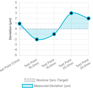
We utilize a set of Master Gauge Blocks (Grade 0 or 1) to verify accuracy across the full travel of the screw.- Test Points: Select at least 5 points across the range (e.g., 5.1mm, 10.3mm, 15.0mm, 20.2mm, 25.0mm). Using “non-round” numbers helps detect errors in the thimble’s graduation.
- Procedure: Wring the gauge block to a precision surface plate. Place the micrometer base over the block and take a reading.
Step 3: Checking Interchangeable Rods
This is where many micrometer calibration services differentiate themselves. Each rod must be calibrated individually.- If you have a 25-50mm rod, you must use a 25mm gauge block as the “starting zero.”
- The error found in the 25-50mm rod must not exceed the manufacturer’s specified tolerance (usually ±2 to ±4 microns).
Step 4: Parallelism and Flatness
- Base Flatness: Use an optical flat and monochromatic light. The number of interference fringes tells us the flatness. More than 2-3 fringes indicate the base needs lapping.
- Spindle Flatness: The measuring tip of the rod must be perfectly flat and perpendicular to the axis of travel.
Metrological Data Visualization
Visualizing accuracy verification and standard uncertainty budgeting.
Linearity & Accuracy Verification
Sample data plotting target depth vs actual readout error over 25mm travel.
Typical Uncertainty Budget
Distribution of standard error sources in dimensional metrology.

5. Understanding Measurement Uncertainty
A professional calibration certificate doesn’t just list “Pass” or “Fail.” It provides a calculated Uncertainty Budget, which includes:- Repeatability (Type A): Variation from multiple measurements of the same point.
- Resolution (Type B): The smallest increment the tool can display.
- Master Gauge Uncertainty: The known error of the reference blocks used.
- Thermal Effects: Residual error from temperature deviations.
6. Expert Tips for Equipment Longevity (EEAT Perspective)
Having overseen thousands of calibration cycles, I recommend these “field-proven” habits to maintain your instrument’s integrity between formal service dates:- The “Ratchet Only” Rule: Never tighten the thimble by hand. Always use the ratchet stop or friction thimble. Human finger pressure varies and can flex the instrument’s frame, leading to inconsistent readings.
- Storage Orientation: Store the micrometer with the rod removed or retracted. Never store it with the measuring face pressed tightly against the base, as this can lead to “cold welding” or permanent tension in the screw.
- Rod Matching: Treat each rod as a unique partner to the micrometer head. Avoid “borrowing” rods from other sets, as the seating depths vary slightly between units.
- Zero-Check Frequency: Check your zero point at the start of every shift and every time you change a measuring rod. It takes 30 seconds but saves hours of rework.
7. Frequently Asked Questions (FAQ)
Q1: How often should I calibrate my depth micrometer?
- A: For high-precision manufacturing, a 12-month cycle is standard. However, if the tool is used daily in a harsh environment, a 6-month interval is safer. Always recalibrate immediately if the tool is dropped.
Q2: Can I calibrate my own depth micrometer internally?
- A: Yes, provided you have Grade 0 gauge blocks, a certified surface plate, and a controlled environment. However, for ISO 9001 compliance, your internal procedure must be validated, and your masters must have external, traceable calibration.
Q3: What should I do if my interchangeable rods are showing different errors?
- A: This usually indicates wear at the rod’s seating point or the spindle’s internal socket. Clean both thoroughly. If the error persists, the rods may need to be “shimmed” or replaced by a professional service.
Q4: Is a digital depth micrometer more accurate than an analog one?
- A: Not necessarily. Digital displays reduce “reading error” (human error in interpreting lines), but the mechanical accuracy depends entirely on the screw pitch and the quality of the rods.
Q5: Why does my reading change when I move the micrometer slightly on the surface?
- A: This suggests a lack of Parallelism or a non-flat base. If the base is bowed, it will “rock,” changing the distance between the spindle and the reference surface.
8. Conclusion: The Path to Zero-Error Manufacturing
Calibration is the bridge between a “good guess” and a “proven fact.” When you invest in professional micrometer calibration services, you aren’t just paying for a sticker and a certificate; you are buying the confidence that every depth measurement taken in your facility is accurate, traceable, and defensible. Don’t let “accumulated error” erode your profit margins and reputation. Ensure your instruments are performing to their highest potential. Ready to certify your precision? Contact our ISO 17025 Accredited Laboratory today for a comprehensive quote on Depth Micrometer Calibration.Frequently asked questions
What is Depth Micrometer Calibration?
How often should a Depth Micrometer be calibrated?
What standards apply to Depth Micrometer Calibration?
What is included on the certificate?
Can you calibrate the Depth Micrometer on-site?
Need Depth Micrometer calibration?
ANAB-accredited, NIST-traceable, fast turnaround — in-lab or on-site across the USA.
Contact us for a quoteReferences & industry standards
- ISO/IEC 17025 testing & calibration laboratory requirements
- NIST calibration services and measurement traceability
- NIST Dimensional Metrology Group
- A2LA / ANAB accreditation for calibration laboratories
External standards bodies. Techmaster Electronics is an ISO/IEC 17025-accredited, NIST-traceable calibration laboratory.

Khanh Nguyen is the Marketing Manager at Techmaster Electronics, a B2B marketing leader covering the test & measurement and ISO/IEC 17025 accredited calibration industry across the US and Vietnam markets.
