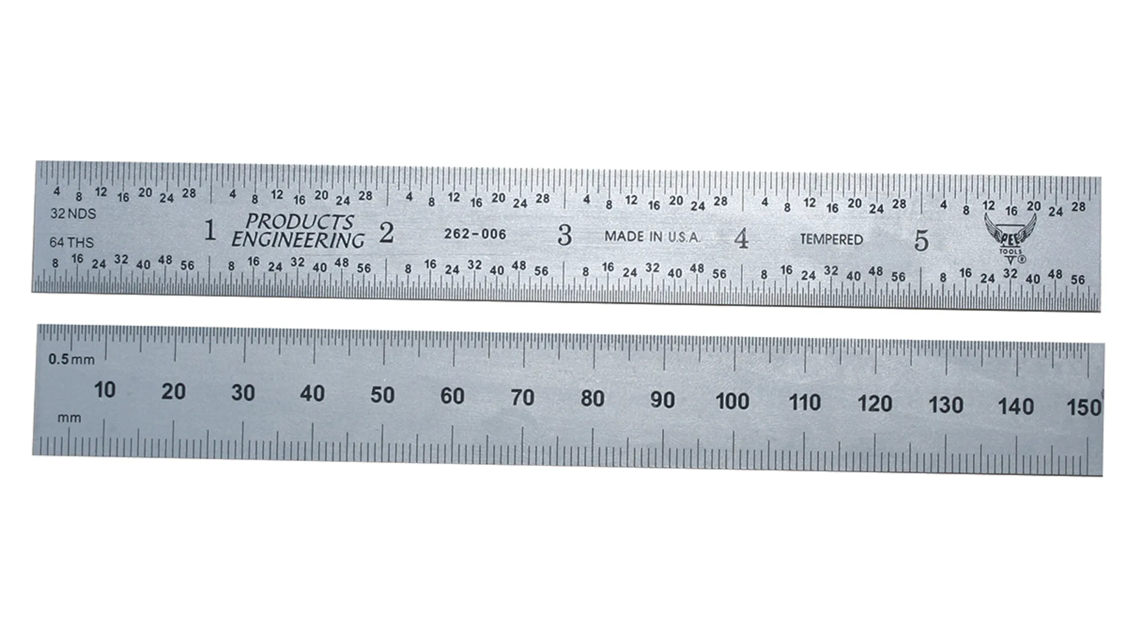
In various fields, from engineering to woodworking, accuracy in measurement is paramount. A seemingly simple tool like a steel ruler plays a crucial role in achieving this precision. However, like any measuring instrument, steel rulers require regular calibration to maintain their accuracy. This post will delve into the importance of Steel Ruler Calibration, the process involved, and why it matters for your projects.

1. Why is steel ruler calibration important?
Accurate measurements are crucial in precision-based industries where even minor deviations can lead to significant errors. Over time, the engraved lines can become less clear, the ruler’s edges may become worn, or the ruler may bend slightly, all leading to measurement errors. Steel ruler calibration is crucial to ensure that your measurements are reliable and accurate. Calibration is important whether the ruler is new or in service.
2. Understanding the Components of a Steel Ruler
- Before diving into the calibration process, it’s essential to understand the different parts of a steel ruler
- End Edge: The square end of the ruler, which is the working edge
- Side Edge: The long edge of the ruler
- Engraved Lines: The markings on the ruler that indicate measurements
- Suspension Hole: A semi-circular hole at the non-working end, often used for storage
3. The steel ruler calibration process
The steel ruler calibration process involves several checks and measurements, as per the ITTC guidelines. These checks help to identify any deviations from the ruler’s original specifications. Here’s a detailed breakdown:
3.1. Exterior Inspection
- The ruler’s end, side edges, and back must be smooth, without any burrs or filings.
- The ruler should not have any mechanical damage, rust, or clear spots that may affect its usage.
- The lines must be clear, perpendicular to the side, and without any visible breaks. Lines indicating half mm, mm, half cm, and cm must have different lengths.
- The scale division of the steel ruler should start at the end edge, with centimeter units marked, and the symbol “cm” should be marked at the position of the nominal whole length.
- The manufacturer’s name, scale division value, and order number must be noted clearly.
- This visual inspection can be done by comparing the ruler to a sample block for surface roughness. If needed, a surface roughness meter can be used. Other visual inspections can be done by eye.
3.2. Flatness of the Ruler Face
- Use a certified gauge block or a master scale with a known level of precision as the reference standard. For example, a ruler between 150-500mm long should have a flatness of 0.25mm, while a 2000mm long ruler can have a flatness of up to 0.60mm.
- The ruler is placed on a first-class leveling ruler or plane, and a first-class plug gauge is used to check for gaps. If the gauge passes, the ruler is not up to standard.
3.3. Elasticity
- The ruler is bent into a curve with a 250mm radius and then released. It should not have any plastic deformation.
- After being bent, the ruler is calibrated based on the method for face flatness.
3.4. Linearity of End and Side Edges
- The end and side edges must meet specific linearity requirements. For example, the end edge of a 150 mm ruler should have a linearity within 0.03 mm, and the side edge should be within 0.10 mm.
- The ruler’s edges are placed against a leveling ruler or plane, and a first-class plug gauge is used to check for gaps.
3.5. Verticality of End and Side Edges
- The end edge must be perpendicular to the side edge within specific limits. For example, a 150 mm ruler should have a verticality within 0.04 mm.
- The ruler is placed on a second-class leveling ruler, and a first-class square is used to check the perpendicularity.
3.6. Thickness of the Side Edge
- The ruler is placed horizontally on a first class leveling ruler with the engraved surface facing downwards, and a first class plug gauge of 0.2 and 0.3mm are used for comparison.
3.7. Arc Radius
- The arc radius at the intersection of the end and side edges should not exceed 0.2mm for a new ruler.
- This can be observed visually or calibrated using a tool microscope.
3.8. Width and Difference Between Lines
- The width of the lines and the difference between them should meet specific requirements. For example, on a 150mm ruler, the width of the lines should be 0.10 – 0.20mm, and the width difference should not exceed 0.04mm.
- A reading microscope with a scale division value of 0.01mm is used for calibration.
3.9. Error of Indication
- The indication error of the whole length of the ruler and from any line to the end edge or the line at the end edge should not exceed specified values. For example, a 150mm ruler should not exceed an error of +/- 0.10mm for the whole length. The error between the end side and the first line is +/- 0.08mm.
- The indication error between any two lines of the steel ruler should also not exceed specified values.
- For whole length calibration, a third-grade standard metal line ruler and a steel ruler calibration table are used. The ruler is aligned with the standard ruler and the error is read using a magnifier. For rulers longer than 1000mm, the ruler can be divided into sections to compare to the standard ruler.
- For the error of the first half-millimeter and millimeter, a reading microscope with a scale division value of 0.01mm can be used.
