

Optimizing Production Precision: The Vital Role of Digital Dimensional Measurement Tools

In the precision-driven world of Industry 4.0, even a few micrometers can separate a high-quality component from industrial scrap. In sectors such as aerospace, medical devices, and semiconductor manufacturing, minor measurement errors can quickly lead to costly failures. Digital indicators serve as the “eyes” of quality control, but their accuracy depends entirely on proper Digital Indicator Calibration. Without regular calibration, even the most advanced instruments can produce misleading data. Ultimately, calibration is not just a maintenance task—it is the foundation of reliable measurement and consistent product quality.
1. Defining the Digital Indicator: The Evolution of Dimensional Metrology
1.1 What is a Digital Indicator?
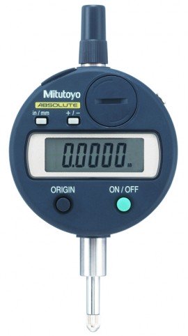
A Digital Indicator is a precision instrument designed to measure linear distances, displacements, and tolerances. It belongs to the DIMENSIONAL metrology category—one of the foundational pillars of industrial measurement. Notably, unlike its predecessor, the mechanical dial indicator, which relies on a complex series of gears and levers to move a needle, the digital version utilizes electronic sensors. These sensors provide a direct numerical readout on an LCD screen.
By converting physical spindle movement into digital data, these tools eliminate “parallax error.” This term refers to the misreading of a needle’s position based on the viewer’s angle. Therefore, this transition from subjective observation to objective data represents the cornerstone of modern quality assurance.
1.2 The Core Technology: How It Works
Modern digital indicators typically operate using one of two advanced sensing technologies. First, many devices use Capacitive Encoders. This system utilizes a series of glass or plastic scales with etched electrodes. As the spindle moves, the mobile sensor changes its position relative to the fixed scale. This action alters the electrical capacitance. Subsequently, a microprocessor calculates this change and converts it into a distance measurement.
Second, high-end models often employ Optical Encoders. These units use a light source and a photo-detector to read tiny graduations on a glass scale. Interestingly, this method offers even more resistance to electromagnetic interference than capacitive systems do.
2. Practical Applications: Where Precision Meets Production
Run-out & Flatness
Measuring axial/radial deviation in shafts and verifying surface flatness after precision machining.
Go/No-Go Inspection
Setting tolerance limits for rapid batch testing on assembly lines to minimize defect rates.
SPC Data Logging
Exporting data for Statistical Process Control to track error trends and prevent mass production failures.
Digital indicators serve as more than mere “rulers”; they act as dynamic diagnostic tools throughout the manufacturing lifecycle.
2.1 Run-out and Flatness Inspection
In mechanical engineering, “Run-out” describes the inaccuracy of rotating mechanical systems. For instance, if a car’s crankshaft has a run-out error, it will cause vibration and premature engine wear. To solve this, a technician mounts a digital indicator on a magnetic base. The tool then detects deviations as the shaft rotates, providing the Total Indicator Runout (TIR). Similarly, inspectors use these devices to verify the flatness of machined surfaces. This ensures that mating parts fit together without gaps.
2.2 Comparative Measurement and Go/No-Go Testing
On a fast-moving production line, checking every dimension manually proves impossible. However, digital indicators allow for “Comparative Measurement.” A master part first sets a “Zero” point. Then, the operator measures every subsequent part against this zero. Many digital indicators also feature built-in tolerance lights. These lights show green for “Pass” and red for “Fail,” which allows technicians to perform Go/No-Go inspections in seconds.
2.3 SPC (Statistical Process Control) Integration
The “Digital” aspect of a Digital Indicator provides the most value when the tool connects to a network. Most professional models feature data output ports, such as USB or Wireless. Consequently, the tool sends measurements directly to a central database.
By analyzing this data, manufacturers can identify “drift.” This term describes the gradual change in dimensions that tool wear or machine heating causes. Therefore, managers can take corrective action before a part goes out of tolerance.
3. Why Calibration is the “Soul” of Measurement
In DIMENSIONAL metrology, tools are highly susceptible to THERMODYNAMIC effects. Minimal temperature shifts can cause material expansion, leading to cumulative errors. Calibration ensures these variances are accounted for using high-precision Gauge Blocks.
| Correcting Mechanical Wear | Compensating for spindle wear after thousands of contact measurement cycles. |
| Global Traceability | Ensuring your measurements are traceable to international standards (NIST, NPL, etc.). |
| ISO Compliance | Obtaining accredited certificates required for ISO 9001 and IATF 16949 audits. |
Owning a world-class digital indicator does not guarantee accuracy. Over time, all instruments “drift” due to environmental factors and mechanical wear. Calibration defines the process of comparing the instrument against a known standard to determine its actual performance.
3.1 Thermodynamic Effects: The Enemy of Dimension
In the DIMENSIONAL field, temperature acts as a constant adversary. Metal expands when it heats up and contracts when it cools down. For this reason, professional calibration labs strictly maintain a temperature of 20 ± 1°C. If a technician uses a tool in a hot factory without proper calibration, the readings could be off by several microns. This error happens simply because the tool’s own internal components underwent thermal expansion.
3.2 Correcting Mechanical Wear and Tear
Unlike ELECTRICAL or RF/MICROWAVE calibration, which deals with intangible signals, dimensional calibration must account for physical friction. The contact tip of a digital indicator eventually wears down through constant use. Furthermore, the internal spindle can develop “play” or friction spots. Calibration detects these issues by testing “Repeatability” and “Hysteresis.” These tests ensure the tool reads the same value regardless of whether the measurement increases or decreases.
3.3 Regulatory and Legal Compliance
For industries like automotive (IATF 16949) or medical devices (ISO 13485), calibration constitutes a legal requirement. A calibration certificate provides a “Traceability Chain” back to national standards. Without this documentation, a manufacturer cannot prove their products meet safety specifications. Ultimately, this lack of proof can lead to rejected shipments or legal liability.
4. The Standard 5-Step Calibration Process
Cleaning & Visual Inspection
Remove dust, oil, and contaminants from all critical measurement surfaces.
Thermal Stabilization
Maintain laboratory conditions at the standard temperature of 20 ± 1°C.
Reference Comparison
Compare measurements against high-accuracy reference standards (Gauge Blocks).
Certification & Labeling
Analyze measurement uncertainty and apply a valid calibration certification label.
A professional, ISO-standard calibration of a digital indicator involves a rigorous, multi-point inspection.
-
Environmental Stabilization: The technician leaves the tool in the calibration lab for several hours. This allows the materials to “soak” in the $20^\circ C$ temperature and stabilize.
-
Visual and Functional Check: The staff checks for scratches on the LCD, verifies smooth spindle movement, and examines the contact tip’s integrity.
-
Accuracy Testing with Gauge Blocks: The technician tests the tool against high-precision Gauge Blocks. These ceramic or steel blocks feature sub-micron accuracy.
-
Error Mapping: The lab checks the tool at multiple points across its entire range to ensure linearity.
-
Uncertainty Calculation: The final certificate does more than just say “Pass.” It provides the Uncertainty of Measurement. This data tells the user exactly how much “doubt” exists in the measurement.
Conclusion: Precision as a Competitive Advantage
In today’s global market, “good enough” no longer suffices. Investing in high-quality digital indicators and a robust Digital Indicator Calibration program represents a smart investment in brand reputation and operational efficiency. By mastering the science of dimensional measurement and maintaining regular Digital Indicator Calibration, manufacturers can significantly reduce scrap rates, improve process capability, and confidently satisfy the most demanding ISO audits.
Do you need expert assistance with Digital Indicator Calibration, Dimensional, RF/Microwave, or Electrical calibration? Our ISO/IEC 17025 accredited laboratory offers both on-site and in-lab services, ensuring your measurement equipment consistently delivers accurate, reliable, and traceable results—so your operations always perform at their peak.
Need to Enhance Your Production Accuracy?
We provide ISO/IEC 17025 accredited calibration services for Dimensional, Electrical, and RF/Microwave equipment.
