

RF Power Sensors: Master of Precision Measurement and the Vital Role of Power Sensor Calibration
In the era of 5G connectivity, modern radar systems, and satellite telecommunications, determining exact transmission power is critical. The Power Sensor serves as the “gold standard” for measuring RF and Microwave energy within a system. However, at high frequencies, impedance mismatches and the natural aging of semiconductor components can lead to measurement errors of hundreds of milliwatts. Consequently, the power sensor Calibration process is not just an option—it is a mandatory requirement to ensure that broadcasting infrastructure remains stable, efficient, and compliant with international standards.
1. How High-Frequency Power Sensors Operate
Modern RF power sensors convert high-frequency electromagnetic energy into a DC signal using two primary sensing technologies:
Thermocouple Sensors
True RMS measurement, waveform-independent, ideal for average power accuracy.
Diode Detectors
High sensitivity and fast response for pulse and peak power detection.
Sensor Linearity Visualization
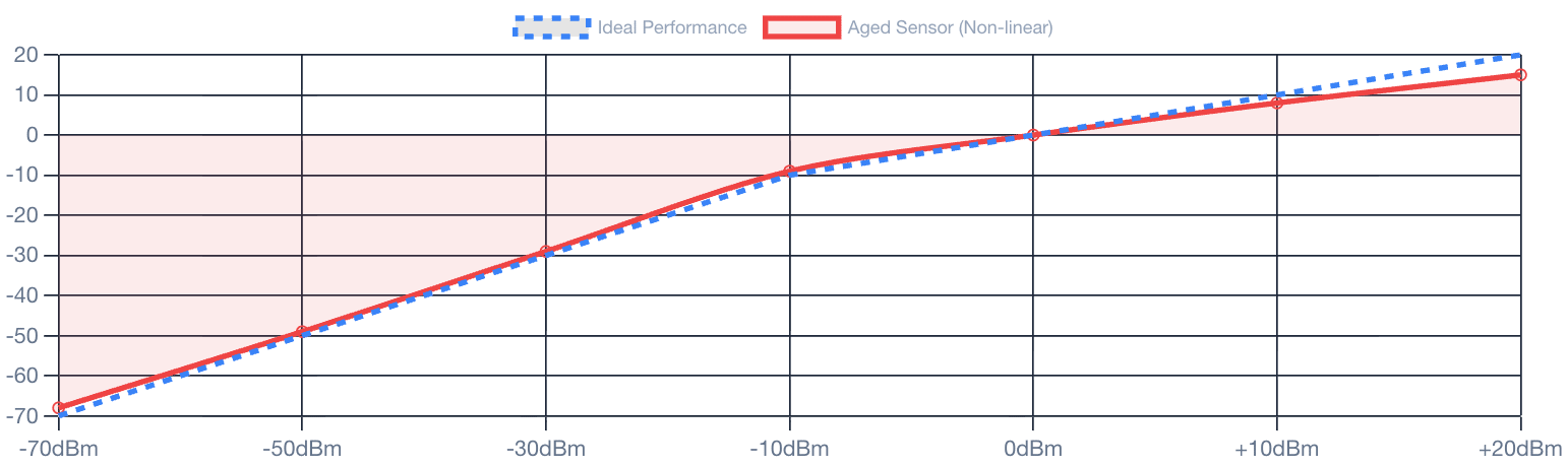
To understand the necessity of calibration, we must first examine how these devices “perceive” energy. Modern power sensors typically utilize one of two primary technologies: Thermocouples or Diodes.
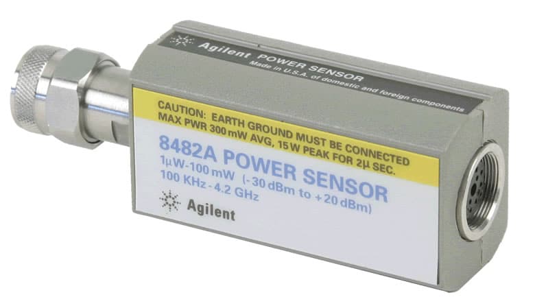
Initially, RF energy enters the sensor’s connector. At this point, the conversion element transforms high-frequency energy into a very small DC voltage. Subsequently, internal signal processing circuitry amplifies and calculates this value into units like dBm or mW. However, these components are extremely sensitive to ambient temperature and input power overloads. Over time, the sensor’s response characteristics drift, causing the displayed value to deviate from reality. This is where power sensor Calibration comes in, comparing the device against a reference standard to redefine its Calibration Factors (Cal Factors).
2. Practical Applications in High-Tech Industries
📡
Telecom Infrastructure
🏭
RF Manufacturing
✈️
Radar & Aerospace
🔬
R&D Laboratories
A power sensor is the most accurate tool available for measuring absolute power, far surpassing the capabilities of a Spectrum Analyzer in this specific regard.
2.1. Telecommunications Maintenance and Base Station Testing
In mobile infrastructure, the output power of a Base Station must be strictly controlled. If the power is too low, the coverage area shrinks; if it is too high, it causes interference with neighboring stations and reduces the lifespan of the power amplifier. Technicians use power sensors to verify the actual energy levels at the antenna input, ensuring service quality remains optimal.
2.2. Wireless Device and RF Component Manufacturing
On production lines for Wi-Fi chips, Bluetooth modules, or RF filters, power sensors are used to calibrate the output levels of the devices under test. This ensures that every product leaving the factory complies with international radio emission regulations.
2.3. Radar Systems and Aerospace
In defense and aviation, radar accuracy determines target identification capabilities. Power sensors help technicians measure both peak pulse power and average power in radar systems, ensuring the transmitted signal has enough energy to return from targets hundreds of kilometers away.
2.4. Laboratory Research and Metrology
In R&D facilities, these sensors serve as a reference for calibrating other measurement tools. Due to their extremely low measurement uncertainty, power sensors are the benchmark for verifying “Insertion Loss” in cables, connectors, and attenuators.
3. Why Power Sensor Calibration is Absolutely Critical
A minor error in RF power measurement can lead to a catastrophic chain reaction in system performance. The power sensor Calibration process addresses several vital issues:
-
Compensating for Mismatch Errors: At high frequencies, impedance differences between the source and the sensor create standing waves. Calibration determines the sensor’s reflection coefficient, allowing for the minimization of these mismatch errors.
-
Defining Frequency-Specific Cal Factors: Every sensor’s sensitivity varies across different frequencies. Calibration provides a data table (Calibration Chart) that allows the user to compensate for errors across the entire range, from kHz to dozens of GHz.
-
Ensuring International Traceability: For measurement results to be globally recognized, the device must be calibrated against national standards (such as NIST). This is crucial for international trade and defense contracts.
-
Detecting Hidden Damage: The calibration process can identify issues such as worn connectors or “leaky” diodes, allowing for repairs before the device fails completely in the field.
4. The Professional RF Laboratory Calibration Procedure
01 — Connector Inspection
02 — Power Reference
03 — Frequency Sweep
04 — Uncertainty Analysis
The power sensor Calibration process requires expensive specialized equipment and a strictly controlled environment:
-
Connector Inspection: Technicians use high-magnification microscopes to inspect Type-N or SMA connectors. A single scratch can significantly alter impedance at high frequencies.
-
Power Reference Verification: The sensor is connected to a 50 MHz (typically 1.00 mW) power reference to establish an initial baseline.
-
Frequency and Amplitude Sweep: Using a precision signal generator and a standard reference sensor, technicians perform a comparison across dozens of frequency points.
-
Linearity Testing: The lab ensures the sensor responds accurately from extremely low power levels (-70 dBm) up to high power levels (+20 dBm).
-
Uncertainty Analysis: Finally, a detailed report is generated, documenting the deviations and the reliability of the measurements.
5. Maintenance Tips to Preserve Accuracy After Calibration
To ensure the results of your power sensor Calibration remain valid for as long as possible, follow these best practices:
-
Use a Torque Wrench: Always use a calibrated torque wrench to tighten connectors. This prevents over-tightening (which deforms pins) or under-tightening (which causes signal noise).
-
Avoid Thermal Shock and Impact: Internal thermocouple elements are delicate. Avoid physical drops or sudden temperature changes.
-
Never Overload the Sensor: Accidentally applying power beyond the sensor’s limit will instantly destroy the diode or thermocouple element.
