
Metrology guide · ISO/IEC 17025 · ANAB-accredited
Digital Test Gauge Calibration
Digital Test Gauge Calibration verifies a Digital Test Gauge against NIST-traceable standards under ISO/IEC 17025. Techmaster performs a documented multi-point check, reports measurement uncertainty, and issues an ANAB-accredited certificate — in-lab or on-site across the USA.
ANAB accredited ISO/IEC 17025 NIST traceable
ISO 17025Accredited method
NISTTraceability
12 moTypical interval
ANABAccreditation
In this guide
Accuracy across the range
Typical as-found results: the indicated error at each test point stays inside the acceptance tolerance band, with measurement uncertainty reported per point.
How Digital Test Gauge calibration works
- Intake & visual inspection
- Environmental stabilization
- As-found measurement
- Comparison to NIST-traceable standards
- Adjustment if required
- As-left results & certificate
Your calibration, covered
In-lab calibrationAccredited bench service with pickup
On-site calibrationWe calibrate at your facility
Expedited turnaroundRush options to cut downtime
Accredited certificateANAB ISO 17025 with uncertainty
In-lab vs on-site calibration
In-lab calibration
- Accredited bench with full reference standards
- Best achievable measurement uncertainties
- Pickup & return logistics handled
- Ideal for precision and reference work
On-site calibration
- We calibrate the Digital Test Gauge at your facility
- No shipping risk or transit downtime
- As-found data captured before any move
- Ideal for fixed, large or sensitive assets
In-depth guide
1. Introduction: The High Cost of “Small” Measurement Errors
In the field of technical services, digital test gauge calibration is paramount, as a “high-precision” instrument can become a significant liability if not properly controlled. A classic case occurred at a large thermal power plant: a technician performed a digital reference gauge calibration check using a Fluke 700G31 as a master reference to set safety valves on a primary steam line. The device displayed a “Pass” result, but it had not been calibrated for 14 months. Subsequent laboratory analysis revealed a non-linear drift of 0.85% F.S. at the upper range, caused by sensor fatigue from pressure spikes. The consequence? The safety valves were set far too high, leading to localized pipe deformation, tens of thousands of dollars in emergency repair costs, and extensive unplanned downtime. Calibration is not merely an administrative hurdle; it is the line between operational safety and catastrophic failure. Whether you utilize an Additel 681, Crystal XP2i, or Fluke 700G, understanding the nuances of digital pressure measurement is critical.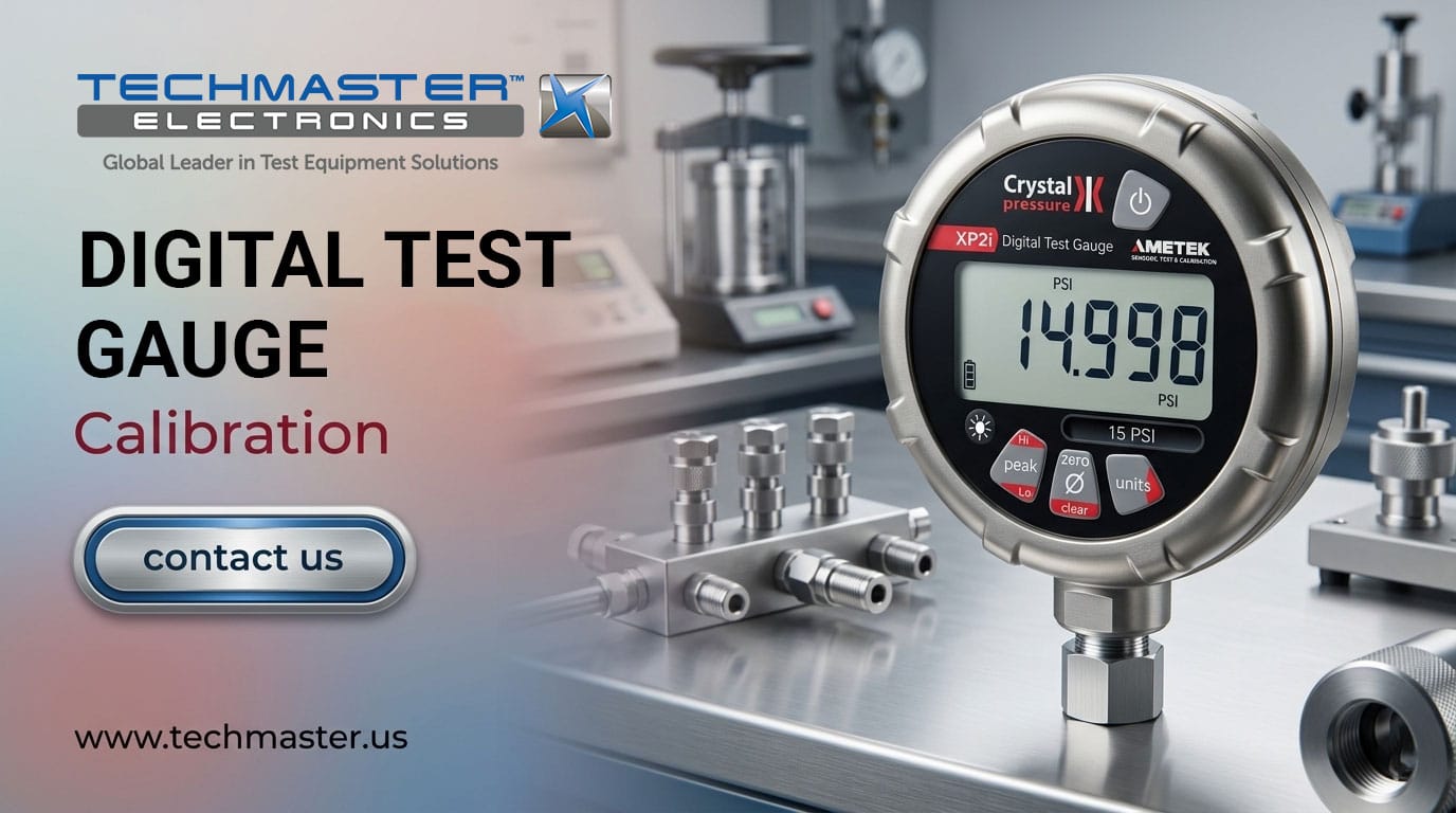
2. Real-World Context: Challenges for Digital Gauges in the Field
Digital gauges are a sophisticated blend of piezoresistive or capacitive sensor technology. However, unlike traditional mechanical gauges, they are prone to “silent” failures. In demanding industrial environments—ranging from high-humidity shipyards to the extreme heat of metallurgical plants—electronic components face unique stressors:- Thermal Hysteresis: Sudden temperature fluctuations cause the silicon diaphragm to expand and contract at different rates than its protective housing, leading to a zero-point shift.
- Overpressure Fatigue: Even if pressure doesn’t immediately destroy the sensor, repeatedly hitting 110% of the range causes micro-stretching of the sensing element, resulting in permanent linearity errors.
- Battery Voltage Sag: On older models, low battery voltage can cause erratic A/D conversion, displaying “ghost” fluctuations that don’t actually exist in the pressure line.
3. Technical Body: Calibration Process according to ISO/IEC 17025
Quick Answer: How is a Digital Reference Gauge Calibrated?
The standard process involves comparing the Unit Under Test (UUT) against a higher-accuracy reference, typically a Deadweight Tester (DWT) or a High-Precision Pressure Controller, at 5 to 11 points across the full scale. Performing a thorough digital reference gauge calibration ensures that the trace of measurement remains within acceptable tolerances. This process quantifies error, repeatability, and hysteresis to ensure the device meets its stated accuracy class (e.g., 0.05% F.S.).Step-by-Step Protocol (Tailored for Additel 681 & Fluke 700G)
Step 1: Pre-Conditioning & Thermal Stabilization
Digital sensors require a “warm-up” period. The device should be placed in the Lab environment (23°C ± 2°C) for at least 2 hours. Then, exercise the sensor by applying maximum pressure 3 times to “wake up” the diaphragm after long periods of inactivity.Step 2: Zero-Point Establishment
Vent the system to atmospheric pressure. In high-precision measurements, one must account for Local Gravity (g) and Head Level Correction. If the reference gauge is placed 10cm higher than the UUT, it creates a measurable error in hydraulic systems.Step 3: Ascending & Descending Measurement Cycles
Proper digital test gauge calibration requires a rigorous cycle of at least 5 points (0% – 25% – 50% – 75% – 100%).- Ascending: Checks the linearity of the sensor.
- Descending: Crucial for determining Hysteresis—the difference in readings when approaching the same pressure point from an increasing vs. decreasing direction.
Step 4: Data Analysis (Simulated Data Table)
| Test Point (PSI) | Reference (DWT) | UUT Reading (PSI) | Deviation (PSI) | Tolerance (0.05% FS) | Field Observation |
|---|---|---|---|---|---|
| 0 | 0.000 | 0.002 | +0.002 | ±0.015 | Common Zero Shift |
| 750 | 750.000 | 750.012 | +0.012 | ±0.015 | Stable |
| 1500 | 1500.000 | 1500.022 | +0.022 | ±0.015 | FAIL (Linearity Error) |
| 2250 | 2250.000 | 2250.018 | +0.018 | ±0.015 | FAIL |
| 3000 | 3000.000 | 3000.005 | +0.005 | ±0.015 | Recovered at Full Scale |
Field Discovery: The “Oil Contamination” Trap
A common issue: Cross-contamination of incompatible media. In pharmaceutical facilities, “Clean Service” digital gauges (used for Nitrogen lines) are sometimes mistakenly used on hydraulic systems. A microscopic film of oil remains inside the sensor port. When returned to the gas line, this oil acts as a dampener, causing a 3-second lag in pressure response and a 0.2% offset. Expert Tip: Always use dedicated oil-to-air separators or separate manifold systems for different media during a digital reference gauge calibration.4. Expert Advisory: Maintenance Hacks for Longevity
Strategy for Tropical Humidity
In environments where humidity frequently exceeds 85%, even IP67-rated models like the Additel 681 can suffer from moisture buildup in the pressure port threads, leading to galvanic corrosion.- Solution: Apply a very small amount of PTFE-based lubricant to the threads, but never allow it to touch the internal face of the sensor.
- Storage: Store reference gauges in a rugged hard-shell case with oversized silica gel packets, replaced monthly.
Pre-Calibration Check: The Digital “Tap Test”
While you don’t tap the glass of a digital gauge like a mechanical one, you should perform a Stability Check. Increase pressure to 50% and hold for 60 seconds. If the digits change continuously (creep), internal seals may be leaking or the sensor diaphragm is experiencing “material creep.”5. FAQ: Technical Q&A
1. Why does my Additel 681 drift faster during summer months?
Quick Answer: High ambient temperatures exceed the sensor’s internal compensation coefficients. Technical Detail: Although digital gauges have “Active Temperature Compensation,” they are calibrated to a specific curve. Extreme heat (above 40°C) creates “Residual Thermal Error.” Even a 0.01%/°C coefficient accumulates significantly on a 3000 PSI device.2. Can I calibrate my digital gauge using another digital gauge?
Quick Answer: Yes, but only if the reference is at least 4 times more accurate (The 4:1 TUR Rule). Technical Detail: If the UUT has 0.1% accuracy, the reference must be at least 0.025%. Without this ratio, the Measurement Uncertainty is too high to provide a meaningful “Pass/Fail” conclusion.3. How often should a Master Gauge be calibrated?
Quick Answer: The standard interval is 12 months, but high-usage field devices should be checked every 6 months. Technical Detail: If a device is used daily as a transfer standard, its risk profile increases. We recommend a monthly “Cross-Check” against another gauge to detect sudden drift early.4. Does the “Zero” button affect calibration results?
Quick Answer: It affects the starting point (offset) but does not fix the slope (span) of the characteristic curve. Technical Detail: Pressing “Zero” at atmospheric pressure resets the baseline. However, it cannot correct linearity errors at 50% or 100% of the range. If you need to “Zero” more than 0.5% of the range, the sensor is likely mechanically damaged.5. Why does my digital gauge show a different result than the analog gauge on the same line?
Quick Answer: Due to differences in resolution, Parallax error in the analog gauge, and the digital gauge’s high sampling rate. Technical Detail: Most analog gauges are Grade A (1% to 2% error). A digital master gauge (0.05%) will always be more reliable, whereas the analog gauge is limited by mechanical friction and the observer’s viewing angle.6. Technical Terms
TRACEABILITY: The property of a measurement result whereby the result can be related to a reference (usually national or international standards) through a documented unbroken chain of calibrations, each contributing to the measurement uncertainty. TEST UNCERTAINTY RATIO (TUR): The ratio between the tolerance limit of the device being calibrated and the expanded uncertainty of the calibration system. A 4:1 ratio is the industry gold standard.7. Conclusion
Precision is not accidental; it is the result of rigorous adherence to metrological standards. A digital test gauge is only as valuable as its valid calibration certificate and the operator’s depth of understanding.Ensure your equipment always meets “Master” standards. Schedule ISO 17025 Calibration Now.
Frequently asked questions
What is Digital Test Gauge Calibration?
Digital Test Gauge Calibration is the documented comparison of a Digital Test Gauge against NIST-traceable reference standards under ISO/IEC 17025, measuring its error and measurement uncertainty and confirming it performs within tolerance.
How often should a Digital Test Gauge be calibrated?
Most quality systems calibrate a Digital Test Gauge every 12 months, and sooner after repair, overload or heavy use. Follow the manufacturer specification and your ISO 9001/13485/AS9100 program.
What standards apply to Digital Test Gauge Calibration?
Calibration is performed under ISO/IEC 17025 with NIST-traceable references and the relevant manufacturer specification. Techmaster is ANAB-accredited.
What is included on the certificate?
An ANAB-accredited ISO/IEC 17025 certificate with as-found and as-left results and the measurement uncertainty for each point.
Can you calibrate the Digital Test Gauge on-site?
Yes. Techmaster offers in-lab calibration with pickup and on-site service across the USA to minimize downtime.
Need Digital Test Gauge calibration?
ANAB-accredited, NIST-traceable, fast turnaround — in-lab or on-site across the USA.
Contact us for a quoteReferences & industry standards
- ISO/IEC 17025 testing & calibration laboratory requirements
- NIST calibration services and measurement traceability
- A2LA / ANAB accreditation for calibration laboratories
External standards bodies. Techmaster Electronics is an ISO/IEC 17025-accredited, NIST-traceable calibration laboratory.
