
Industrial environments rely on absolute precision to maintain safety, ensure product quality, and pass regulatory audits. However, differential pressure instruments are highly sensitive and prone to progressive measurement drift due to harsh operating conditions. Consequently, utilizing a professional ISO 17025 pressure calibration service is the only way to prevent costly process failures, eliminate progressive measurement drift, and maintain operational integrity.
1. Why Uncalibrated Differential Pressure Gauges Threaten Industrial Safety and Quality
Uncalibrated pressure instruments cause critical safety hazards, regulatory non-compliance, and severe quality failures due to unmanaged sensor drift. Consequently, implementing a routine calibration program is essential. Ultimately, this practice guarantees accurate process monitoring, prevents unexpected shutdown events, and maintains total plant compliance. Specifically, uncalibrated pressure instruments pose severe risks to industrial facilities, leading to catastrophic compliance failures, product contamination, and undetected system drift. For example, in high-stakes environments like pharmaceutical cleanrooms or petrochemical pipelines, a minor deviation can compromise entire production batches and trigger regulatory shut-downs. Moreover, this progressive drift slowly erodes manufacturing accuracy, driving up operational waste and exposing your facility to severe safety hazards. Therefore, implementing a systematic, traceable differential manometer calibration routine eliminates these operational risks. As a result, relying on an accredited ISO 17025 pressure calibration service ensures your systems maintain absolute measurement integrity and meet strict quality criteria.2. How a Differential Manometer Works and Its Role in Plant Efficiency
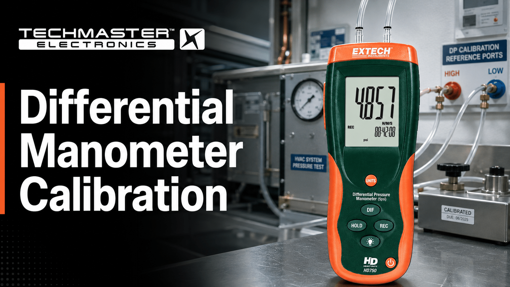
A differential manometer measures pressure differences between two process points to optimize volumetric flow, fluid levels, and cleanroom gradients. Consequently, any uncalibrated reading compromises total system safety. Therefore, keeping these instruments accurate is vital for preventing operational waste and sustaining efficiency. Specifically, a differential manometer measures the physical difference in pressure between two distinct points in a process system. For this reason, this instrument features two input ports, designated as high-pressure and low-pressure sides, which direct fluid toward a central sensing element. Furthermore, the device operates by exposing a flexible internal diaphragm, silicon sensor, or fluid column to these dual pressures simultaneously. Subsequently, the physical deflection of the diaphragm is converted into a readable measurement, either mechanically or electronically. Ultimately, this measurement is critical for monitoring volumetric flow rates, liquid levels in pressurized vessels, and cleanroom pressure gradients. Therefore, without precise differential pressure gauge calibration, minor physical changes in the sensor lead to skewed process data and system inefficiency.3. Demystifying the Metrological Challenges of Differential Pressure (DP) Measurement
Measuring differential pressure accurately requires understanding physical challenges like zero-point drift and static line pressure effects. Consequently, these forces deform internal sensors and introduce measurement errors. Therefore, technicians must utilize specialized procedures to isolate and correct these systemic metrological deviations.Differential Pressure (DP): The difference in physical force per unit area between two distinct pressure points in a fluid system. It is calculated by subtracting the reference pressure on the low side from the applied pressure on the high side.Furthermore, zero-point drift in differential manometers is primarily caused by physical diaphragm overpressure, extreme temperature fluctuations, and mechanical stress from incorrect installation orientation. Specifically, these factors physically deform internal sensing elements over time, which shifts the baseline reference and compromises overall reading accuracy.
What Causes Zero-Point Drift in Differential Manometers?
Zero-point drift stems from mechanical deformation of internal sensors due to temperature spikes or pressure overloads. Consequently, this physical deformation introduces a permanent shift in baseline measurements, requiring corrective differential manometer calibration. Therefore, understanding these physical stressors is vital for preventative maintenance. Specifically, zero-point drift stems from mechanical deformation of internal sensors due to temperature spikes or pressure overloads. As a result, this physical deformation introduces a permanent shift in baseline measurements, requiring corrective differential manometer calibration. For instance, overpressure events occur when pressure on one side exceeds the maximum design limit of the sensor diaphragm. Moreover, even temporary pressure spikes cause permanent mechanical deformation, leading to permanent zero-point shifts. Additionally, environmental temperature changes expand or contract the internal fill fluids and physical metal components of the sensor housing. Subsequently, this thermal movement alters the mechanical spring rate of the diaphragm, skewing low-range measurements. In addition, incorrect mounting angles introduce gravity-induced head errors because the mass of the internal components pulls on the sensor. Therefore, technicians must perform differential manometer calibration in the exact physical orientation as the field installation.Why Static Line Pressure Alters Differential Sensor Accuracy
Static line pressure alters sensor accuracy by compressing internal parts and shifting the physical zero point. Therefore, technicians must simulate real operating line pressure during the differential pressure calibration procedure. Ultimately, this specialized test prevents major measurement offsets when the device returns to service. Indeed, static line pressure impacts differential sensors by exerting symmetrical forces that compress internal sensor components, altering their mechanical sensitivity. Consequently, high baseline pressures can distort the physical diaphragm, causing substantial measurement calibration shifts that require specialized high-pressure offset adjustments. For example, in typical field applications, the static line pressure is significantly higher than the differential pressure being measured. To illustrate, a transmitter might measure a small differential pressure of 50 millibar while operating under a static pressure of 100 bar. As a direct result, this immense physical compression shifts the physical zero point and span characteristics of the measurement sensor. Therefore, technicians must conduct the differential pressure calibration procedure under simulated operating static pressures to counteract this systemic offset. On the contrary, failing to account for static pressure effects during laboratory testing leads to significant errors when the instrument is returned to active field service. Ultimately, working with a premier ISO 17025 pressure calibration service helps mitigate these static pressure errors through advanced simulation equipment.4. Step-by-Step: How to Execute a Precise Differential Pressure Gauge Calibration
Executing a precise calibration involves systematic pre-inspection, mounting, safe manifold isolation, pressure testing, and metrological adjustment. Consequently, following these steps ensures repeatable data and audit compliance. Therefore, technicians must use high-accuracy reference standards and document all intermediate and final measurements.Measurement Uncertainty: A non-negative parameter characterizing the dispersion of the quantity values being attributed to a measurand, based on the information used. It quantifies the level of physical doubt remaining in a measurement result.Specifically, this procedure outlines the exact steps required to verify and adjust a differential pressure instrument against a certified master reference standard to restore measurement accuracy. Ultimately, following a standardized process ensures repeatable data, safety, and strict regulatory compliance.
Step 1: Pre-Calibration Inspection and Level Setup Mounting
Pre-calibration setup requires inspecting the physical chassis, cleaning the ports, and leveling the instrument precisely. Consequently, this step eliminates gravity-induced gravity errors and positioning offsets. Therefore, technicians must verify structural integrity before applying any calibration pressure. Initially, this phase prepares the instrument for testing. For this reason, technicians must confirm alignment during this setup phase to prevent gravity-induced errors during the differential pressure calibration procedure.- First, inspect the casing, ports, and terminals for physical damage or process contamination.
- Subsequently, mount the device securely in its exact operational orientation using a bubble level.
- Finally, clean all connections to prevent physical particulates from entering the pressure reference system.
Step 2: Safe Isolation of the Instrument Using a Manifold
Isolating the instrument requires operating manifold valves in a strict sequence to prevent devastating single-sided overpressure events. Consequently, this action protects the sensitive diaphragm from physical rupture. Therefore, technicians must vent trapped pressure slowly before decoupling. Primarily, this safety measure protects the internal sensor from destructive pressure spikes. For this reason, technicians must manipulate manifold valves in a sequence that guarantees complete safety and isolation.- First, open the equalizing valve to equalize pressure across both sensor chambers.
- Next, close the high-pressure and low-pressure process valves to isolate the device.
- Finally, vent all trapped process pressure to the atmosphere before connecting calibration lines.
Step 3: Integrating the High-Accuracy Reference Standard
Integrating the reference standard connects the high-precision pressure pump to the high side of the sensor. Consequently, this establishes a sealed pneumatic calibration circuit. Therefore, technicians must leave the low side vented to serve as a barometric reference. Specifically, this step links the system to an ultra-precise calibration instrument. Indeed, a certified ISO 17025 pressure calibration service relies on reference standards that are far more accurate than the target gauge.- First, connect the high-pressure port to the output of the high-precision pressure generator.
- Next, leave the low-pressure port open to the atmosphere to establish a barometric zero reference.
- Finally, connect a high-accuracy digital reference gauge inline with the generator to monitor applied forces.
Step 4: Executing a 5-Point Calibration Cycle to Detect Hysteresis
A 5-point calibration cycle applies test pressures in rising and falling sequences to calculate linearity and hysteresis. Consequently, this exercise identifies physical sensor lag and structural fatigue. Therefore, technicians must allow the pressure to stabilize at each setpoint. Specifically, this cycle exercises the sensor across its operating range. For this reason, technicians must apply pressure smoothly and allow the readings to stabilize at every checkpoint.- First, apply test pressures at 0%, 25%, 50%, 75%, and 100% of full scale.
- Next, record the rising calibration readings against the digital reference standard at each point.
- Finally, decrease the pressure back down through 75%, 50%, 25%, and 0% to evaluate hysteresis.
Step 5: Recording Metrological Data, Zeroing, and Target Adjustments
Recording metrological data involves logging initial readings, adjusting span errors, and documenting the final as-left state. Consequently, this process restores accuracy and establishes traceability. Therefore, all calibration details must be recorded on the official certificate. Ultimately, this final task logs metrological performance and corrects deviations. As a result, technicians can ensure that the instrument conforms to standard quality specifications prior to re-installation.- First, compare the raw as-found data against the manufacturer-specified calibration tolerance limits.
- Next, adjust the internal zero and span configurations if any point exceeds maximum limits.
- Finally, conduct a secondary test cycle to capture the final as-left data for the certificate.
5. Navigating Compliance Standards: ISO/IEC 17025 and Metrological Traceability
Compliance requires maintaining an unbroken chain of traceable measurements to national standards and evaluating measurement uncertainty. Consequently, this documentation satisfies auditors during strict industrial quality checks. Therefore, facilities should choose accredited calibration services to protect operational integrity. Specifically, a certified calibration standard ensures that your pressure instruments are verified using an unbroken chain of comparisons back to primary national standards. For this reason, this formal trace-level structure is required to satisfy industrial quality standards and pass rigorous third-party audits.Why NIST Traceability Is Non-Negotiable for Industrial Audits
NIST traceability proves your calibration measurements are linked to internationally recognized physical standards. Consequently, this documentation validates your compliance standing during regulatory inspections. Therefore, maintaining detailed trace logs is critical for global trade and product quality. Specifically, NIST traceability links industrial measurements back to primary physical standards, proving to regulatory auditors that your differential pressure gauge calibration is globally valid and legally compliant. Indeed, this direct link to recognized physical standards is essential for maintaining global trade compatibility and ensuring consistent product quality across different manufacturing facilities. Furthermore, without documentable NIST traceability, calibration data lacks legal standing during regulatory audits or safety investigations. For this reason, process facilities must maintain structured records showing the unbroken calibration chain of every master standard used in their testing. Moreover, choosing an ISO 17025 pressure calibration service ensures that the performing laboratory maintains a rigorous, audited quality system and possesses proven technical competence. Specifically, this international standard governs laboratory management, staff training, equipment maintenance, and calculation procedures.Evaluating “Measurement Uncertainty” on Your Calibration Certificates
Measurement uncertainty defines the statistical boundaries of doubt for each test point on your certificate. Consequently, simple pass-fail results are not enough for highly sensitive operations. Therefore, quality managers must analyze uncertainty data to verify process tolerance limits. Specifically, measurement uncertainty calculations quantify the exact margins of error present during a calibration run, accounting for environmental factors, reference standards, and human variance. On the contrary, relying solely on simple pass-fail errors is insufficient for high-risk industrial processes where minor deviations cause severe system failures. For instance, the expanded measurement uncertainty is calculated as the coverage factor multiplied by the combined standard uncertainty, represented as plus or minus U = k times u. In this calculation, k is the coverage factor, which is typically set equal to 2 to achieve an approximate 95% confidence level. Moreover, every professional calibration certificate must display this expanded measurement uncertainty value alongside the recorded calibration data points. Therefore, evaluating uncertainty with the help of a competent ISO 17025 pressure calibration service ensures that your process margins remain fully compliant under actual operating conditions.6. Onsite vs. Laboratory Calibration: Choosing the Best Strategy for Your Facility
Choosing between onsite and laboratory calibration involves balancing operational uptime against environmental precision requirements. Consequently, each option serves distinct plant roles. Therefore, managers must assess instrument criticalities before scheduling active calibration services. Indeed, facilities must balance operational downtime with environmental precision when deciding between performing calibrations directly in the field or sending instruments to an accredited laboratory. As a result, both approaches offer unique advantages depending on the specific application, accuracy requirements, and physical location of the equipment.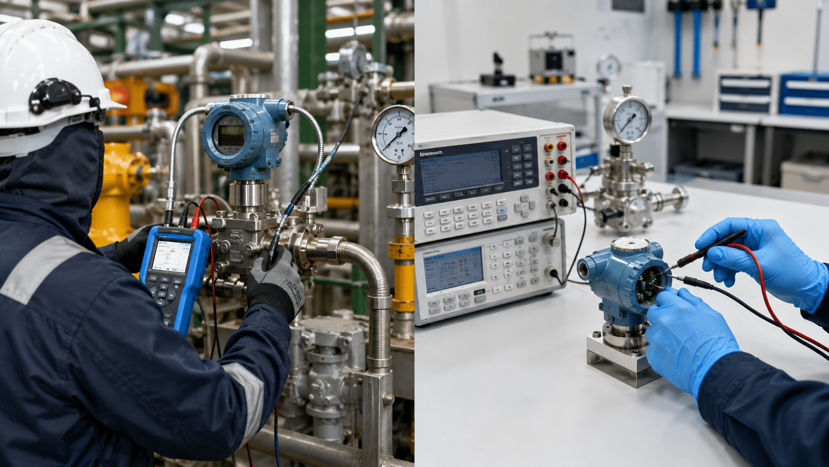
Minimizing Downtime: Onsite Calibration for Cleanrooms and HVAC Systems
Onsite calibration allows technicians to test the entire measurement loop directly in the field. Consequently, this minimizes operational downtime and eliminates physical transport damage risks. Therefore, it is ideal for standard cleanroom and mechanical setups. Specifically, field calibration verifies the complete measurement loop in its actual operating environment, making it ideal for low-pressure HVAC systems where uninstalling instruments is risky. Consequently, this process eliminates the physical risks associated with dismantling sensitive pressure lines and transport damage.- First, it minimizes operational downtime by completing the calibration process directly on the production floor or inside mechanical rooms.
- Second, it verifies the complete instrumentation loop, including the physical tubing, electrical wiring, and digital control system readouts.
- Finally, it validates performance under actual environmental conditions, matching the humidity, ambient temperature, and vibration of daily operations.
Maximizing Accuracy: Laboratory Calibration for High-Precision Master Gauges
Laboratory calibration offers highly stable, controlled environments with minimal environmental noise. Consequently, this allows for the lowest possible measurement uncertainty on master instruments. Therefore, delicate standard gauges must be calibrated in-house. Specifically, highly sensitive instruments require the stable climate of an accredited laboratory, where specialized equipment provides the highest level of standard instrument calibration. For this reason, controlled laboratories maintain minimal environmental noise, allowing technicians to achieve extremely low measurement uncertainty. Consequently, sending your reference standards to an accredited ISO 17025 pressure calibration service ensures that environmental noise and stability are strictly controlled.- First, it features precise climatic controls, maintaining room temperature at 20 °C plus or minus 2 °C and relative humidity below 65% to eliminate environmental drift.
- Second, it utilizes high-precision primary standards, such as piston gauges and automated pressure controllers, which are too delicate for field use.
- Finally, it provides a sterile, dust-free environment that prevents internal contamination of ultra-low-range differential pressure sensors.
7. Expert Advisory: Preventive Maintenance and Long-Term Reliability
Preventative maintenance requires regular leak checking, line purging, pre-test stabilization, and climate-controlled instrument storage. Consequently, these practices prevent unexpected out-of-tolerance sensor issues. Therefore, technicians should enforce these metrological guidelines. Ultimately, maximizing the operational lifespan and reliability of differential pressure instruments requires strict adherence to preventive maintenance protocols and environmental controls. As a result, implementing these expert recommendations reduces the frequency of out-of-tolerance calibration events and improves overall plant safety.Standard Maintenance Protocols to Prevent Gauge Failures
Routine maintenance protocols include checking for piping leaks, purging water from dry gas lines, and checking wiring. Consequently, these simple checks prevent system errors and drift. Therefore, maintenance teams must run these assessments weekly. Specifically, technicians must perform visual and functional checks on all differential instruments to detect signs of early physical degradation. Consequently, regular inspection of process seals and manifold connections prevents systemic measurement errors.- First, inspect all piping and manifold connections for slow pneumatic leaks using a certified, non-corrosive leak detection fluid.
- Next, purge accumulated moisture or physical condensate from dry-gas differential lines to prevent liquid head errors.
- Finally, verify the physical electrical connections to ensure there is no corrosion or loose wiring on the transmitter terminals.
Mandatory Pre-Calibration Preparation and Thermal Stabilization
Pre-calibration preparation includes holding instruments in the lab for thermal stabilization and pre-conditioning the diaphragm. Consequently, this steps eliminates structural tension errors in the metal sensor. Therefore, diagnostics must be completed before logging official data. Specifically, before starting any differential pressure calibration procedure, specific baseline checks must be executed to ensure the instrument is ready for testing. As a result, preparing the unit correctly prevents false calibration failures and ensures data consistency.- First, allow the instrument to stabilize at the ambient laboratory temperature for at least 2 hours before beginning any measurements.
- Next, exercise the sensor diaphragm by applying full-scale pressure 3 times before recording any formal calibration data points.
- Finally, verify that the reference standards are fully warmed up and have completed their own mandatory self-test diagnostics.
Optimal Storage Conditions for Sensitive Pressure Instruments
Proper storage requires climate-controlled cabinets, vibration isolation, and physical port caps to protect sensitive diaphragms. Consequently, this prevents physical corrosion and premature spring degradation. Therefore, unused instruments must remain protected. Indeed, differential manometers are highly sensitive to extreme environmental conditions, which degrade internal electronics and physical sensor diaphragms. For this reason, proper storage and environmental controls prevent baseline drift when instruments are not in active service.- First, store uninstalled instruments in a climate-controlled cabinet maintained at 15 °C to 25 °C with relative humidity below 60%.
- Second, avoid storing gauges in areas subject to strong magnetic fields, direct sunlight, or high-frequency mechanical vibrations.
- Finally, keep protective shipping caps installed on both pressure ports to prevent dust, insects, and moisture from entering the sensor.
8. Quick Reference: Calibration Standards for Prominent Industrial Models
This reference table maps widely utilized industrial differential pressure instruments to their respective manufacturers, primary applications, and relevant international calibration guidelines.| Model | Manufacturer | Typical Industrial Application | Calibration Standard/Guideline |
|---|---|---|---|
| Rosemount 3051S | Emerson | Oil and Gas Flow Measurement | EURAMET cg-17 / BS EN 837 |
| EJX110A | Yokogawa | Chemical Process Control | ISO 17025 / JIS B7505 |
| Series 2000 Magnehelic | Dwyer | Cleanroom Differential Pressure | DKD-R 6-1 / ASTM E220 |
| DPG40 | Wika | Filter Monitoring and HVAC | EURAMET cg-17 / EN 837 |
9. Troubleshooting and Frequently Asked Questions (FAQs)
Troubleshooting differential gauges requires identifying optimal calibration intervals, test uncertainty ratios, thermal errors, and line isolation steps. Consequently, knowing these answers helps technicians quickly isolate errors in the field. Therefore, review these metrological answers.FAQ 1: How often should a differential manometer be calibrated?
Differential manometers must be calibrated every 12 months under standard operating conditions to prevent measurement drift. However, high-vibration environments, extreme temperatures, or regulatory requirements may require a shorter 6-month calibration interval to ensure safety.FAQ 2: What is the ideal Test Uncertainty Ratio (TUR) for pressure calibration?
The ideal Test Uncertainty Ratio (TUR) for industrial pressure calibration is 4:1 or greater. Specifically, this means that the reference standard used must be at least 4 times more accurate than the maximum allowable tolerance of the device under test. Indeed, an expert ISO 17025 pressure calibration service uses master standards that guarantee this required ratio during every test.FAQ 3: How does temperature change affect low-range DP gauges?
Temperature changes expand or contract the internal sensor components and fill fluids, altering the physical tension on the measuring diaphragm. Consequently, this thermal movement shifts the baseline reading, causing severe measurement errors in ultra-low-range differential pressure gauges.FAQ 4: Can we calibrate a differential manometer without isolating it?
No, a differential manometer cannot be calibrated safely or accurately without fully isolating it from the active process line. Indeed, attempting to calibrate an unisolated device introduces high process pressure spikes, risking physical injury and destroying the sensor.FAQ 5: How does static line pressure affect differential pressure gauge calibration?
Static line pressure exerts equal physical force across the entire sensor capsule, compressing internal components and altering diaphragm tension. Consequently, this compression shifts the physical zero point and calibration span, requiring correction under simulated operational static pressure.10. Partner with an ISO 17025 Accredited Calibration Provider
Partnering with an accredited ISO 17025 lab provides validated measurement traceability, expert staff, and minimized risk of compliance audits. Consequently, this relationship secures plant operations and eliminates drift issues. Therefore, request a calibration check today. Indeed, maintaining the precision of your differential measurement instruments is critical for regulatory compliance, product quality, and system safety. Furthermore, ignoring subtle measurement drift leads to manufacturing errors, failed audits, and expensive operational downtime. As a result, relying on an expert calibration provider protects your business from these systemic quality control risks. Ultimately, partnering with an accredited laboratory ensures your instruments are verified using state-of-the-art reference equipment and fully documented traceability. To guarantee the reliability of your pressure instruments, schedule your professional ISO 17025 pressure calibration service today and secure an audit-ready facility.References & industry standards
- ISO/IEC 17025 testing & calibration laboratory requirements
- NIST calibration services and measurement traceability
- NIST Pressure and Vacuum Group
- A2LA / ANAB accreditation for calibration laboratories
External standards bodies. Techmaster Electronics is an ISO/IEC 17025-accredited, NIST-traceable calibration laboratory.

Calibration engineer at Techmaster Electronics, ISO/IEC 17025 accredited laboratory with 35+ years of metrology expertise.
