

RF Power Meter: The Key to Optimizing Wireless System Performance – The Absolute Necessity of Calibration
In the world of wireless signal transmission, from 5G mobile networks and high-speed Wi-Fi to military radar systems, signal power (RF Power) is the most critical technical parameter. Inaccurate power levels can lead to two serious problems: if too high, it can damage expensive components, cause interference, and violate emission regulations. Conversely, if too low, it degrades network performance, resulting in lost connections and poor service quality. The RF Power Meter is the gold standard, indispensable tool designed to accurately measure radio frequency energy. This device allows engineers to verify, adjust, and maintain complex transmission systems. However, due to the sensitive nature of high-frequency measurements (standing waves, connection loss), routine RF Power Meter Calibration is a mandatory procedure. Calibration confirms the accuracy of the sensor, ensuring that every design and maintenance decision relies on reliable power data.
1. What is an RF Power Meter? The Core Operating Principle
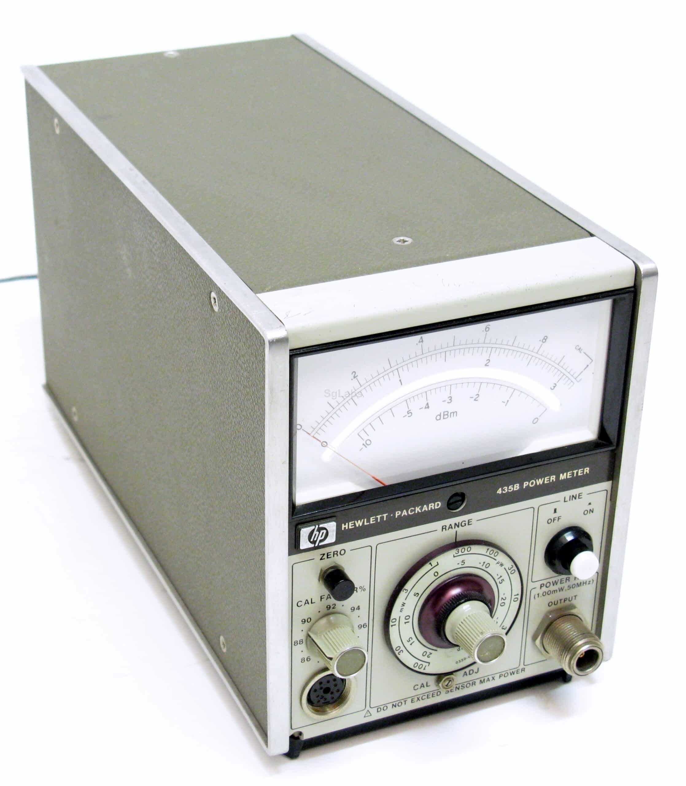
An RF Power Meter is a specialized measuring instrument. We design it to measure the absolute power (typically in Watts or dBm) of an electromagnetic signal in the high-frequency range, from Radio Frequency (RF) to Microwave.
What is an RF Power Meter?
It measures the absolute RF/Microwave power level (Watts/dBm) across wide frequency ranges.
Frequency Range
Covers wide RF/Microwave bands.
Absolute Power
Measures real transmitted energy.
Dynamic Range
Handles µW to high-watt levels.
1.1. Objective and Key Measurement Parameters
-
Objective: To accurately measure transmitted or emitted power. This optimizes performance, ensures regulatory compliance, and protects equipment.
-
Key Measurement Parameters:
-
Absolute Power: Measured in Watts (W) or decibel milliwatts (dBm).
-
Operating Frequency Range: The capability to measure across a broad frequency spectrum (e.g., from $10 \text{ MHz}$ to $18 \text{ GHz}$).
-
Dynamic Range: The ability to measure power from very low levels (microWatts) to very high levels (Watts).
-
1.2. Basic Operating Principle
-
Power Sensor: This is the core component. The sensor converts RF energy into an equivalent DC signal or temperature change.
-
Thermal Sensor Types (Thermocouple/Thermistor): They measure the temperature change caused by RF energy; this provides highly accurate True RMS power measurement.
-
Diode Sensor Types: They use diodes to rectify the RF signal into DC, typically used for lower power ranges.
-
-
Signal Processor: The DC signal from the sensor is sent to the main instrument. The processor applies correction factors (depending on the frequency) and converts the result to dBm or Watt units for display.
The RF Power Safety Zone
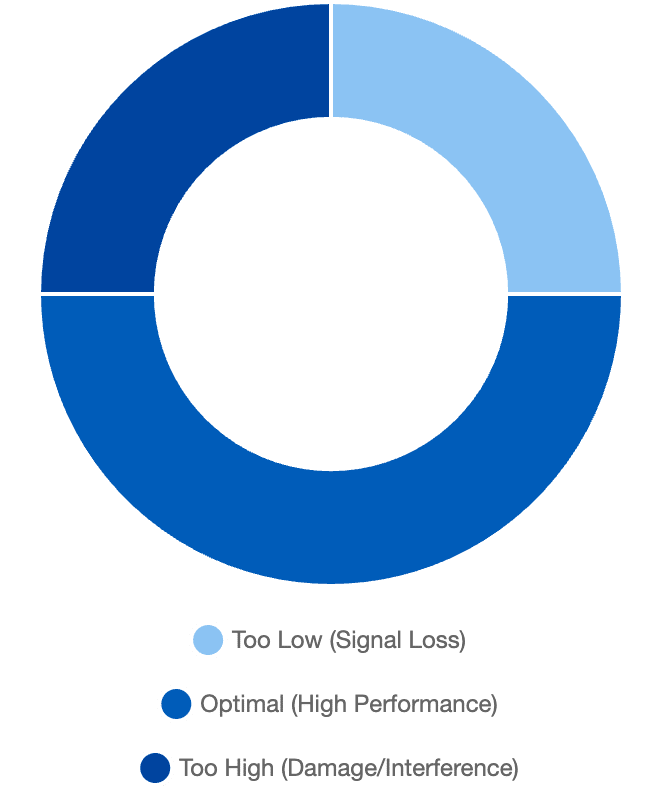
A delicate balance between performance and risk.
2. Vital Applications in Telecommunications and Defense
📶 Telecommunications
Base Stations: Ensures proper channel power for 4G/5G.
Manufacturing: Confirms amplifier output accuracy.
✈️ Defense & Aerospace
Radar: Maintains correct transmission levels.
Satellites: Ensures stable deep-space communication.
🔬 Research & Development
Prototyping: Evaluates RF circuit behavior.
EMC/EMI: Validates compliance standards.
The ability to accurately measure RF power is a key factor for every wireless transmission system.
2.1. Telecommunications and Wireless Networks
-
Base Station Testing: Engineers use this equipment to verify the transmission power of each frequency channel in cellular base stations (2G/3G/4G/5G). This ensures the station operates at the specified power level, maximizing coverage without causing interference.
-
RF Equipment Manufacturing: During the production of amplifiers, transceivers, and other RF components, the RF Power Meter verifies that the product meets the specified output power limits.
2.2. Aerospace and Defense
-
Radar and Satellite Systems: These systems require extremely precise transmit power to ensure operating range and resolution. The RF power meter is mandatory for confirming the performance of radar transmitters or satellite transmission modules.
-
Electromagnetic Compatibility (EMC/EMI) Testing: The power measurement device helps test and ensure compliance with electromagnetic radiation regulations.
2.3. Research and Development (R&D)
-
New Circuit Design: Researchers use this equipment to test the output power, loss, and amplification efficiency of prototype RF/Microwave circuits.
3. The Absolute Role of RF Power Meter Calibration
Power Sensor Drift Over Time
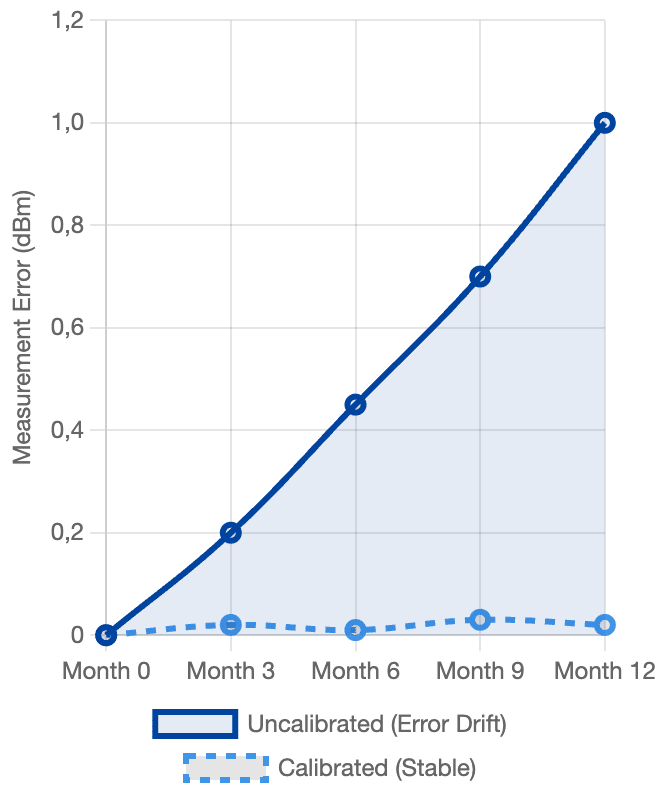
Error increasing over 12 months without calibration.
Impact of Calibration on Accuracy
Margin of error comparison: uncalibrated vs calibrated.
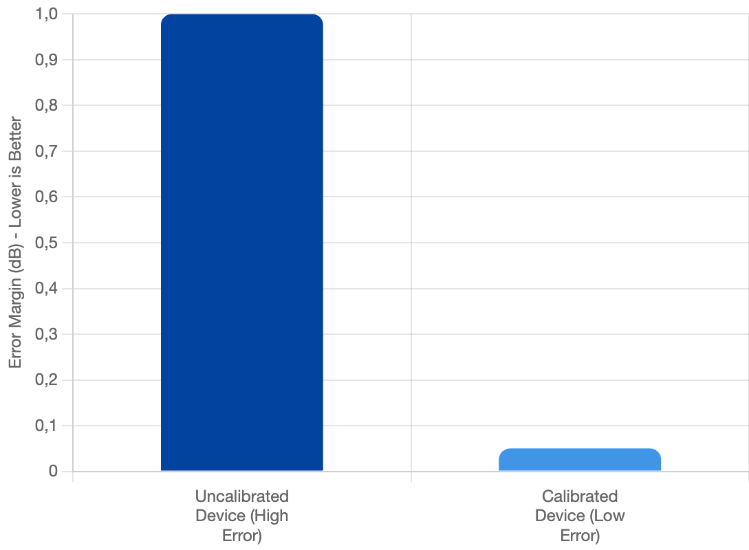
The nature of RF measurement is inherently complex (due to standing waves, temperature, connectors), meaning an inaccurate power measurement can lead to technical and legal disasters. Therefore, RF Power Meter Calibration is paramount.
3.1. Ensuring Accuracy and Consistency
-
Risk of Inaccuracy: RF power sensors are thermal or semiconductor devices. They age, are affected by temperature, and gradually drift over time. An uncalibrated sensor might report an error of $1 \text{ dBm}$—which is equivalent to the actual power being doubled or halved!
-
Frequency Correction: RF Power Meter Calibration determines and precisely applies Correction Factors for each frequency. This ensures the device reads accurately across its entire operating frequency range.
-
Value Verification: Calibration confirms that the displayed power value matches the true power relative to the reference standard.
3.2. Legal Compliance and Asset Protection
-
Emission Regulation Compliance: Regulatory bodies (e.g., FCC) strictly mandate maximum transmission power levels. An inaccurate meter can lead to legal violations and significant fines.
-
Equipment Protection: Inaccurate high-power readings can cause engineers to accidentally overpower amplifiers, leading to damage of multi-million dollar equipment.
-
Audit Certification: Standards like ISO/IEC 17025 mandate that critical measuring equipment must be calibrated. The Calibration Certificate provides legal proof of data integrity.
4. Power Meter Calibration Process
Standard Calibration Procedure
Performed using certified labs and traceable standards.
Reference Source
Uses precise RF generators.
Comparison
Compare sensor and reference.
Correction
Apply updated factors.
Certification
Issue calibrated report.
The process of RF Power Meter Calibration requires specialized laboratories and high-level reference equipment:
-
Reference Source System: We use standard RF/Microwave Signal Sources and highly accurate Reference Standard Transfer Systems, which an accredited national metrology institute has calibrated.
-
Check and Compare: A technician connects the power sensor under calibration to the reference source system. They compare the reading on the device with the known accurate power of the reference source at multiple power levels and frequency points (often dozens of points).
-
Error Determination: The deviation between the displayed value and the reference value is recorded. New Calibration Factors are calculated and programmed into the sensor’s (or main instrument’s) memory.
-
Certification: A Calibration Certificate is issued, confirming the sensor’s accuracy and the next calibration due date.
Conclusion
The RF Power Meter is an indispensable tool. It determines the performance, reliability, and legal compliance of every wireless transmission system. However, for this tool to truly be “gold,” it must undergo periodic RF Power Meter Calibration. This is a mandatory procedure that not only protects expensive assets but also ensures service quality, safeguards consumers, and maintains the stability of global telecommunication systems.
