
FFT Analyzer Calibration
Frequency response at a glance
How FFT Analyzer calibration works
- Intake & visual inspection
- Environmental stabilization
- As-found measurement
- Comparison to NIST-traceable standards
- Adjustment if required
- As-left results & certificate
Your calibration, covered
In-lab vs on-site calibration
In-lab calibration
- Accredited bench with full reference standards
- Best achievable measurement uncertainties
- Pickup & return logistics handled
- Ideal for precision and reference work
On-site calibration
- We calibrate the FFT Analyzer at your facility
- No shipping risk or transit downtime
- As-found data captured before any move
- Ideal for fixed, large or sensitive assets
In-depth guide
FFT Analyzers: Unveiling the Hidden World of Signals and the Vital Role of FFT Analyzer Calibration

In the realm of modern engineering, electrical signals and mechanical vibrations rarely appear as clean, simple waves. Most of the time, they are a chaotic mixture of various frequencies. To understand, diagnose, and fix technical problems, engineers need a way to “look inside” these signals. This is where the Fast Fourier Transform (FFT) Analyzer becomes indispensable. However, the data provided by these complex instruments is only as good as the device’s accuracy. This is why FFT Analyzer Calibration is not just a maintenance task—it is a critical safeguard for technical integrity.
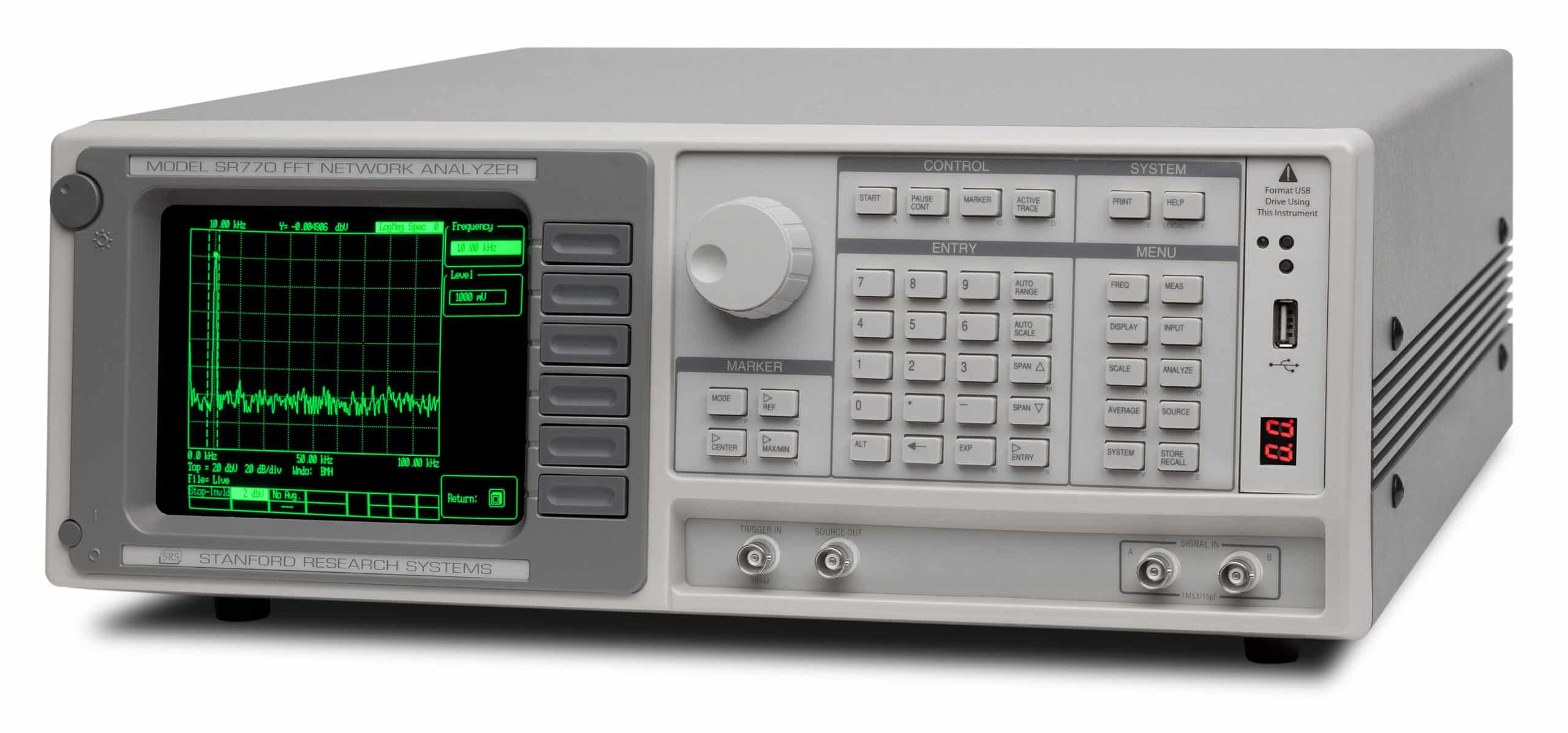
1. The Power of Fast Fourier Transform (FFT)
Imagine listening to a full orchestra. In the time domain, you only hear the total sound level. FFT allows you to separate each instrument — violin, piano, drums — into distinct frequency components.
Instead of viewing a complex sine waveform, FFT displays clear spectral peaks representing actual frequencies. Without proper calibration, those peaks shift — leading to incorrect diagnostics and costly engineering mistakes.
2. Real-World Applications: Where Precision Matters Most
Predictive Maintenance
Detect bearing wear and shaft misalignment before catastrophic failure occurs.
Acoustics & NVH
Identify unwanted noise sources in vehicles through frequency spectrum analysis.
Electronics & Telecom
Measure harmonic distortion (THD), phase noise, and signal integrity.
Structural Engineering
Determine resonance frequencies to prevent dangerous mechanical amplification.
The FFT analyzer is a “gold-standard” instrument across several high-stakes industries.
2.1. Vibration Analysis and Predictive Maintenance (PdM)
In industrial plants, rotating machinery like motors, turbines, and compressors are the lifeblood of production. Every internal component—bearings, gears, shafts—vibrates at a specific “signature” frequency. By using an FFT analyzer, maintenance teams can spot a failing bearing weeks before it actually breaks. However, this relies on seeing very small signals at specific frequencies. FFT Analyzer Calibration ensures that these tiny warning signs are not lost in the background noise of the instrument.
2.2. Noise, Vibration, and Harshness (NVH) in Automotive Engineering
The automotive industry is obsessed with the user experience. Engineers use FFT analyzers to track down the source of “squeaks and rattles.” By analyzing the frequency spectrum, they can tell if a noise is coming from the engine, the exhaust, or the wind hitting the side mirror. Accurate calibration ensures that the decibel (dB) readings meet international safety and comfort standards.
2.3. Audio and Electronics Design
In the world of high-fidelity audio, “purity” is the goal. Engineers use FFT analyzers to measure Total Harmonic Distortion (THD). They look for unwanted “ghost” frequencies that might ruin the sound of an amplifier. A calibrated analyzer allows them to push the limits of audio performance, ensuring that the sound reproduced is exactly what the artist intended.
2.4. Structural Engineering and Material Science
Buildings and bridges have natural resonance frequencies. If wind or an earthquake hits those specific frequencies, the results can be catastrophic. FFT analyzers help structural engineers identify these “danger zones.” In material science, the device helps analyze how new polymers or alloys react to stress. In these cases, measurement accuracy is quite literally a matter of public safety.
3. The Great Myth: “Digital Tools Don’t Drift”
One of the most dangerous misconceptions in modern labs is that digital instruments are always correct. While it is true that the microprocessor calculates the FFT perfectly, the signal must first pass through an analog front-end.
-
Component Aging: Internal amplifiers, resistors, and capacitors change their electrical properties over time.
-
Thermal Effects: High-precision electronics are sensitive to heat. As the internal temperature changes, the gain of the pre-amplifiers can shift.
-
Clock Jitter: The timing of the sampling process depends on a quartz crystal. These crystals “age” and can cause the frequency axis to become inaccurate.
Regular FFT Analyzer Calibration accounts for these physical changes, ensuring the digital output remains anchored to physical reality.
4. What Happens During a Professional FFT Analyzer Calibration?
Frequency Verification
Use a traceable signal generator to confirm internal oscillator stability.
Amplitude Flatness
Sweep across the full frequency range to ensure consistent measurement.
Harmonic Distortion Test
Apply a pure sine signal to verify no artificial harmonics are introduced.
ISO 17025 Certification
Issue a traceable calibration certificate and complete quality documentation.
A professional calibration is a rigorous process conducted in a climate-controlled laboratory, usually following ISO 17025 standards.
Step 1: Frequency Accuracy Verification
The technician uses a high-stability signal generator (often synced to an atomic clock) to feed a precise frequency into the analyzer. They check if the “peak” on the screen appears at exactly the right spot.
Step 2: Amplitude Flatness (Frequency Response)
An analyzer must be accurate across its entire range, from 1 Hz up to 100 kHz or more. The lab performs a “sweep,” ensuring the device measures the same amplitude regardless of the frequency.
Step 3: Dynamic Range and Noise Floor Testing
The lab feeds a pure sine wave into the device and checks for “spurious signals”—noise created by the machine itself. A well-calibrated machine must have a very low “noise floor” to see the smallest signals.
Step 4: Harmonic Distortion Check
If the analyzer itself introduces distortion, it is useless for testing other equipment. Technicians measure the analyzer’s own THD to ensure it meets the manufacturer’s specifications.
Step 5: Phase Accuracy (Multi-channel units)
For devices with multiple inputs, the timing between channels must be perfect. This is essential for “Transfer Function” measurements, which compare an input to an output.
5. Compliance, Standards, and Traceability
In sectors like aerospace, defense, and medical manufacturing, calibration is a legal requirement.
-
ISO 17025 Accreditation: This is the global benchmark for calibration labs. Getting your FFT Analyzer Calibration done at an accredited lab ensures your results are recognized worldwide.
-
NIST Traceability: Traceability means your measurements can be traced back through an unbroken chain to national standards. This is your “legal shield” in case of a product failure or audit.
-
Risk Mitigation: If a bridge fails or a car part is recalled, the first thing investigators look at is the calibration records of the tools used to design them.
6. Pro-Tips: Maintaining Accuracy After Calibration
30-Minute Warm-Up
Allow internal components to stabilize thermally before critical measurements.
High-Quality Cables
Poor shielding can distort signals before they even reach the analyzer.
Stable Environment
Temperature variations significantly affect electronic measurement accuracy.
Firmware Updates
Keep software updated to optimize FFT processing algorithms.
To maximize the value of your FFT Analyzer Calibration, your team should follow these best practices:
-
The 30-Minute Rule: Always allow the instrument to warm up for at least 30 minutes. This allows the internal components to reach thermal equilibrium, reducing drift.
-
Cable Integrity: Never use cheap or damaged BNC cables. A bad cable can introduce reflections and noise that look like signals on your FFT plot.
-
Avoid Input Overload: Exceeding the maximum voltage of the input can “blind” the sensor or even damage the delicate input stage, instantly ruining your calibration.
-
Controlled Environment: If possible, keep your analyzer in a room with stable temperature and humidity. Rapid environmental changes are the enemy of electronic precision.
-
Self-Calibration (Self-Cal): Many modern analyzers have a built-in “Self-Cal” routine. Run this daily, but remember: Self-cal is not a substitute for a full laboratory calibration. It only handles short-term thermal shifts.
7. Choosing the Right Calibration Partner
Not all labs have the specialized equipment to handle high-performance FFT analyzers. When selecting a service provider, ensure they have:
-
Low-distortion signal sources.
-
Traceable frequency standards.
-
Experience with multi-channel phase alignment.
-
Comprehensive reporting that includes “As-Found” and “As-Left” data.
Conclusion
The FFT analyzer is a masterpiece of modern measurement science. It allows us to hear the whispers of failing machines and see the invisible vibrations of our world. But this window into the frequency domain must be kept clear.
Investing in regular FFT Analyzer Calibration is more than just a box to tick for a quality audit. It is an investment in the safety of your structures, the quality of your products, and the reputation of your engineering team. In a world where a few milli-volts or a few Hertz can change everything, make sure your data is the absolute truth.
Frequently asked questions
What is FFT Analyzer Calibration?
How often should a FFT Analyzer be calibrated?
What standards apply to FFT Analyzer Calibration?
What is included on the certificate?
Can you calibrate the FFT Analyzer on-site?
Need FFT Analyzer calibration?
ANAB-accredited, NIST-traceable, fast turnaround — in-lab or on-site across the USA.
Contact us for a quote