

Many manufacturing facilities face a nightmare scenario: a critical batch of components is rejected during a Tier-1 audit because a thread plug gauge calibration was performed incorrectly or the certificates lacked NIST/ISO traceability. When a thread plug gauge drifts—often due to microscopic abrasive wear in high-volume CNC environments—it leads to “false pass” results that compromise structural integrity and risk massive financial penalties. This guide provides the definitive strategic fix, ensuring your thread gage calibration protocols meet the most stringent ISO/IEC 17025 standards and keep your production lines audit-ready.

The Critical Role of Thread Plug Gauges in Modern Manufacturing
Thread plug gauges are the silent sentinels of quality control, ensuring that internal threads meet specific pitch diameter limits. In harsh industrial settings involving coolant spray, metal shavings, and repetitive manual torque, these gauges are subject to mechanical degradation that is often invisible to the naked eye.
Whether you are using a standard 6H metric plug or a specialized Unified National (UN) series, the environmental factors such as ambient temperature fluctuations and surface oxidation can significantly impact the accuracy of your measurements. Understanding how these tools behave under stress is the first step toward a robust metrology program.
Step-by-Step: How to Ensure Your Thread Plug Gauges Meet Global Standards
🧼 Phase 1: The Preparation Protocol
Before any measurements occur, the gauge must be completely free of environmental contaminants. Even residual anti-rust oil can skew precision measurements. The standard requires total contaminant eradication.
🔍 Phase 2: Visual Inspection
A sterile gauge is only half the battle. Under mandatory 10x magnification, technicians actively hunt for “nicks” on the thread crests. This chart visualizes the typical distribution of contaminants and defects found before cleaning.

⚠️ Phase 3: The Butterfly Effect
Why does a tiny nick matter? A single burr on the crest displaces the calibration wires. As the burr size increases, it causes an artificial and exponential increase in the calculated pitch diameter.
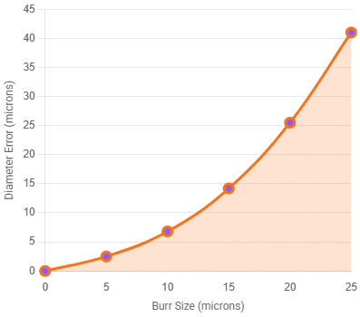
| Burr Size (µm) | Diameter Error (µm) |
|---|---|
| 0 | 0.0 |
| 5 | 2.5 |
| 10 | 6.8 |
| 15 | 14.2 |
| 20 | 25.5 |
| 25 | 41.0 |
To achieve a valid thread gauge calibration certificate, the process must strictly adhere to documented procedures, typically utilizing the “Three-Wire Method” or a high-precision universal length measuring machine (ULM). A professional thread gage calibration workflow ensures that every measurement is repeatable and traceable to international standards.
1. Preparation and Thermal Stabilization
Before any measurements are taken, the gauges and the master equipment must stabilize in a temperature-controlled laboratory (ideally 20°C ± 0.5°C). Even a small temperature difference can cause a measurable expansion in steel gauges, leading to a “failed” result for tight-tolerance threads.
2. Cleaning and Visual Inspection
Remove all traces of anti-rust oil or debris using an ultrasonic cleaner or lint-free wipes with isopropyl alcohol. Under 10x magnification, inspect for “nicks” on the crest of the threads. A single burr can displace the calibration wires, resulting in an artificial increase in the calculated pitch diameter during the thread gage calibration process.
3. The Three-Wire Measurement Method
For most thread gage calibration tasks, we utilize calibrated thread measuring wires. The formula for calculating the pitch diameter (E) is determined as follows:
E = M – w * (1 + 1/sin(a)) + 0.5 * p * cot(a)
Where:
- E is the pitch diameter to be found.
- M is the measurement over the wires.
- w is the diameter of the measuring wires.
- p is the thread pitch.
- a is the thread half-angle (e.g., 30 degrees for metric threads).
4. Direct Measurement via ULM
For high-precision requirements, a Universal Length Machine provides a lower measurement uncertainty by using horizontal contact points and digital scales, eliminating the manual “feel” associated with micrometers.
Definition: Pitch Diameter The diameter of an imaginary cylinder where the width of the thread ridge and the width of the groove are equal. It is the most critical dimension for thread interchangeability.
Traceability, Uncertainty, and Simulated Field Data
A thread gauge calibration certificate is worthless without a statement of uncertainty. In our simulated field study of a high-volume automotive fastener line, we observed a consistent drift pattern.
Case Study: The “Abrasive Drift” Phenomenon
In a facility producing 5,000 units/day, we monitored a Go/No-Go Thread Plug Gauge (M12 x 1.75 6H).
- Initial Calibration: Pitch Diameter at 10.863 (Nominal: 10.863).
- 6-Month Check: Measured 10.858.
- Observation: A drift of -0.005. While still within the wear limit for some, it approached the “danger zone” for high-spec aerospace audits.
- Field Discovery: The technician noted that the “Go” member showed uneven wear at the first three threads—the result of operators “forcing” the gauge into slightly misaligned parts.
Technical Data Comparison Table
| Gauge Specification | Tolerance (Class X) | Measured Value (Lab) | Field Deviation Observed | Audit Risk Status |
|---|---|---|---|---|
| M6 x 1.0 6H (Go) | ±0.008 | 5.352 | -0.003 | Low |
| 1/2-13 UNC 2B (Go) | ±0.0003 | 0.4501 | -0.00015 | Moderate |
| M20 x 2.5 6H (No-Go) | ±0.009 | 18.374 | +0.001 | Low |
| 10-32 UNF 3B (Go) | ±0.0002 | 0.1698 | -0.00025 | CRITICAL |
The “Technician’s Eye”: What is Often Missed During On-Site Inspections
During hundreds of site visits, I have noticed a recurring issue that standard checklists overlook: The “Bell-Mouth” Wear Pattern. Most automated calibration systems measure the center of the thread plug. However, the most significant wear occurs at the front-leading threads. If your calibration service provider only takes a single-point measurement in the middle, they may issue a “Pass” for a gauge that is actually undersized at the entry point. This leads to parts passing inspection that will eventually fail in the field due to loose fitment. Always insist on a three-point measurement (Front, Middle, Back) to detect taper or bell-mouting.
Definition: Traceability The property of a measurement result whereby the result can be related to a reference through a documented unbroken chain of calibrations, each contributing to the measurement uncertainty.
Expert Advisory: Maintaining Long-Term Reliability
Maintenance “Hacks”
- The 360° Rotation Rule: Instruct operators to rotate the gauge 360 degrees when withdrawing it, rather than pulling it straight out. This reduces side-loading wear on the flanks.
- Solvent Selection: Avoid chlorinated solvents which can promote microscopic pitting in high-carbon steel. Use specialized metrology-grade cleaners.
Pre-Calibration Checks
Before sending your tools for thread plug gauge calibration, perform a “rough check” using a master ring gauge. If the “Go” plug feels significantly loose in a certified “Go” ring, it likely needs replacement rather than just recalibration, saving you the cost of a “Fail” certificate.
Storage Conditions
Thread gauges are highly susceptible to corrosion. Store them in VCI (Vapor Corrosion Inhibitor) lined drawers or coat them in a non-hardening synthetic protective wax if they are not used weekly.
FAQ: Common Concerns in Thread Metrology
Why does my thread plug gauge drift faster in high-heat environments?
Answer: Thermal expansion not only changes the measurement during use but accelerated heat cycles can alter the molecular structure of the steel over years, leading to “stress relaxation” and dimensional instability. Furthermore, heat often lowers the viscosity of lubricants, increasing metal-to-metal friction and wear.
How often should I perform thread plug gauge calibration?
Answer: The industry standard is 12 months, but for high-use gauges (over 50 checks per day), a 3-month or 6-month interval is recommended. Base your frequency on “drift data” from previous certificates.
Can a “No-Go” gauge ever wear “out of spec”?
Answer: Yes, though it happens less frequently. If an operator forces a “No-Go” gauge into a hole, the crests can flatten, eventually allowing the gauge to enter a part it should reject.
What is the difference between Class X and Class W tolerances?
Answer: Class W is the highest precision (used for master gauges), while Class X is the standard for working gauges. Using a Class X gauge for a Class W application is a common audit finding.
Does a thread gauge calibration certificate need to show the actual values?
Answer: Yes. For ISO/IEC 17025 compliance, a simple “Pass/Fail” is insufficient. The certificate must show the “As Found” and “As Left” data points along with the expanded uncertainty.
Conclusion: Ensuring Audit Success
Precision is not just a metric; it is a competitive advantage. Ensuring your thread plug gauge calibration is performed by an accredited laboratory with deep technical expertise protects your brand from the catastrophic costs of recalls and audit failures. By implementing the “three-point” inspection and managing thermal stability, you move beyond “commodity” quality control into the realm of elite manufacturing.
The Bottom Line
If you bypass the ultrasonic cleaner or skip the 10x magnification inspection, you aren’t just cutting corners — you are guaranteeing an inaccurate pitch diameter calculation and risking a critical audit failure.
