
Mixed Signal Oscilloscope Calibration…
Accuracy across the range
How Mixed Signal Oscilloscope calibration works
- Intake & visual inspection
- Environmental stabilization
- As-found measurement
- Comparison to NIST-traceable standards
- Adjustment if required
- As-left results & certificate
Your calibration, covered
In-lab vs on-site calibration
In-lab calibration
- Accredited bench with full reference standards
- Best achievable measurement uncertainties
- Pickup & return logistics handled
- Ideal for precision and reference work
On-site calibration
- We calibrate the Mixed Signal Oscilloscope at your facility
- No shipping risk or transit downtime
- As-found data captured before any move
- Ideal for fixed, large or sensitive assets
In-depth guide
1. Introduction: The Hidden Cost of Uncalibrated Mixed Signal Analysis
Imagine spending three weeks debugging a high-speed SPI bus on a prototype, only to realize the 2ns timing lag wasn’t a firmware bug, but a synchronization drift in your equipment. Mixed signal oscilloscope calibration is the only defense against such “ghost” errors; when a device drifts, it creates a false reality where analog transients and digital logic appear decoupled, leading to catastrophic project delays, wasted component costs, and compromised signal integrity. By implementing a rigorous MSO calibration routine, engineers move from “guessing” to “knowing,” transforming an unverified tool into a high-precision diagnostic asset that meets strict ISO 17025 MSO calibration benchmarks. This strategic investment ensures that your onsite oscilloscope calibration doesn’t just check boxes, but actively protects your R&D ROI by guaranteeing absolute phase and amplitude alignment across all channels.
2. Device Overview: MSOs in High-Stress Environments
Mixed Signal Oscilloscopes like the Tektronix MSO58, Keysight Infiniium S-Series, and Rohde & Schwarz RTO6 are marvels of integration, but they are highly sensitive to industrial stressors. In environments with high electromagnetic interference (EMI) or fluctuating thermal loads from nearby server racks, the internal clocking circuitry and ADC (Analog-to-Digital Converter) stages can experience non-linear drift. Unlike standard DSOs, an MSO must maintain a strict timing relationship between its 4-8 analog channels and 16+ digital logic channels. Even a slight degradation in the probe interface or internal termination resistors can lead to “inter-channel skew.” In high-humidity labs, we often observe oxidation on the high-density digital headers, which adds parasitic capacitance, slowing down edge transitions and causing false logic triggers during high-speed bus analysis.3. ISO 17025 MSO Calibration: A Step-by-Step Technical Guide
Step 1: Self-Alignment and Thermal Stabilization
Before any external measurements, the MSO must reach thermal equilibrium (typically 20–30 minutes). We perform a “Signal Path Compensation” (SPC). This internal routine adjusts for gain and offset errors caused by current temperature conditions. If an SPC fails, it is an immediate indicator of a hardware fault.Step 2: Vertical Accuracy (Amplitude & DC Offset)
We use a high-precision DC source (e.g., Fluke 9500B) to verify each analog channel.- Requirement: Accuracy within ±(1.5% to 3%) of the full-scale range.
- Field Protocol: We test multiple V/div settings, as a drift might only manifest at millivolt scales where noise floors interfere with sensitive low-power signals.
Step 3: Horizontal Timing and Timebase Verificaton
The internal clock is compared against a Rubidium or GPS-disciplined oscillator.- Focus Keyphrase Integration: During mixed signal oscilloscope calibration, the timebase accuracy is paramount. A drift of just 5ppm can lead to significant jitter measurements on long-duration captures.
Step 4: Digital-to-Analog Synchronization (The MSO “Heart”)
This is where MSO calibration differs from standard scope service. We inject a synchronized pulse into both an analog channel and a digital logic bit.- Test: Measuring the “skew” between the 50% point of the analog edge and the digital transition.
- Standard: Modern MSOs should show <200ps of inter-channel skew after deskewing.
Traceability & Simulated Technical Analysis
| Parameter | Test Point | Tolerance | Observed Field Deviation (Simulated) |
|---|---|---|---|
| DC Gain Accuracy | 500 mV/div | ±2.0% | 2.15% (Out of Tolerance) |
| Bandwidth (-3dB) | 1 GHz | >707 mV | 680 mV (Roll-off issues) |
| Digital Timing Skew | Analog vs D0 | < 500 ps | 850 ps (Critical Integrity Risk) |
| Trigger Sensitivity | 100 MHz @ 1div | Stable | Intermittent Jitter observed |
Definition Block: Inter-Channel Skew The time delay difference between two or more channels when measuring the same signal. In MSOs, this refers specifically to the lag between analog and digital inputs, which can lead to “race conditions” in decoded data.
The “Technician’s Eye”: Field Discovery
What is often missed during onsite oscilloscope calibration: During a recent site visit to a telecommunications hardware facility, I discovered a recurring “hidden error” in their Tektronix MSO fleet. The analog channels passed calibration perfectly, but the digital logic probes were failing to trigger on 1.8V CMOS logic.Technician’s View: Threshold Voltage Drift
A commonly overlooked error: Digital logic probes failing to trigger correctly because comparator circuits drift after years of usage.
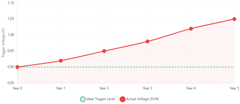
The device assumes it triggers at 0.9V (1.8V CMOS standard), but the actual trigger point is 1.05V.
Consequence: I2C data corruption when running at high speeds.
4. Professional Reliability Hacks
To maintain the results of your ISO 17025 MSO calibration, you must implement a “Zero-Trust” approach to probing. Probes are the most vulnerable part of the measurement system and require more frequent validation than the oscilloscope mainframe itself.- Pre-Calibration Check: Always inspect the “Gold Pins” on the MSO interface. We often see bent pins on the digital headers which cause intermittent “bit-flipping” that software diagnostics can’t detect.
- Maintenance Hack: Use specialized contact cleaner (non-residue) on the BNC connectors. Even a micro-layer of oxidation increases return loss (VSWR) at frequencies above 500MHz, making your signals look “noisier” than they actually are.
- Storage Tip: MSO logic probes should never be stored tightly coiled. Internal micro-coaxial ribbons can fracture, leading to frequency-dependent attenuation that ruins mixed signal oscilloscope calibration results.
5. FAQ: Answer-First Technical Queries
1. Why does my MSO show different timing for the same pulse on Analog vs. Digital? Answer: This is usually due to propagation delay differences in the probes and lack of proper deskewing. Mixed signal oscilloscope calibration aligns these internal paths, but users must still perform a “Probe Deskew” routine at the start of every critical project to account for specific cable lengths. 2. Is onsite oscilloscope calibration as accurate as a lab environment? Answer: Yes, provided the environment is climate-controlled. Professional onsite oscilloscope calibration uses portable high-end calibrators (like the Fluke 9500B) that provide the same traceability as a fixed lab, with the added benefit of testing the equipment in its actual operating thermal state. 3. How often should I calibrate my MSO for high-speed digital projects? Answer: The industry standard is 12 months. However, if you are working on DDR4/5 or high-speed PCIe debugging where timing margins are sub-nanosecond, a 6-month MSO calibration cycle is recommended to account for component aging and clock drift. 4. What is the risk of skipping ISO 17025 MSO calibration? Answer: The primary risk is “False Pass” errors. You might release a product that seems to meet timing specs on your scope, but fails in the field because your measurement tool had a 5% gain error or a 300ps timing offset. 5. Can I use standard logic probes with any MSO? Answer: Generally, no. Digital channels are tuned to specific probe impedances. Using a non-matched probe will invalidate your mixed signal oscilloscope calibration and likely result in severe signal loading, changing the behavior of the circuit you are trying to measure.6. Conclusion: Precision is the Foundation of Innovation
In the world of high-speed electronics, your Mixed Signal Oscilloscope is your only window into the invisible. Ensuring that this window is clear through rigorous mixed signal oscilloscope calibration is not just a maintenance task—it is a critical safeguard for your engineering integrity. By adhering to ISO 17025 MSO calibration standards and utilizing expert onsite oscilloscope calibration services, you eliminate the “Signal Integrity Risk” that haunts complex projects. Don’t let a 200ps drift destroy a million-dollar project; verify your precision today.Ensure Your Signal Integrity Today
Don’t let undetected drifts compromise your R&D projects. Schedule your ISO 17025 accredited MSO calibration now.
Frequently asked questions
What is Mixed Signal Oscilloscope Calibration?
How often should a Mixed Signal Oscilloscope be calibrated?
What standards apply to Mixed Signal Oscilloscope Calibration?
What is included on the certificate?
Can you calibrate the Mixed Signal Oscilloscope on-site?
Need Mixed Signal Oscilloscope calibration?
ANAB-accredited, NIST-traceable, fast turnaround — in-lab or on-site across the USA.
Contact us for a quoteReferences & industry standards
- ISO/IEC 17025 testing & calibration laboratory requirements
- NIST calibration services and measurement traceability
- NIST RF electromagnetics metrology
- A2LA / ANAB accreditation for calibration laboratories
External standards bodies. Techmaster Electronics is an ISO/IEC 17025-accredited, NIST-traceable calibration laboratory.

Khanh Nguyen is the Marketing Manager at Techmaster Electronics, a B2B marketing leader covering the test & measurement and ISO/IEC 17025 accredited calibration industry across the US and Vietnam markets.
