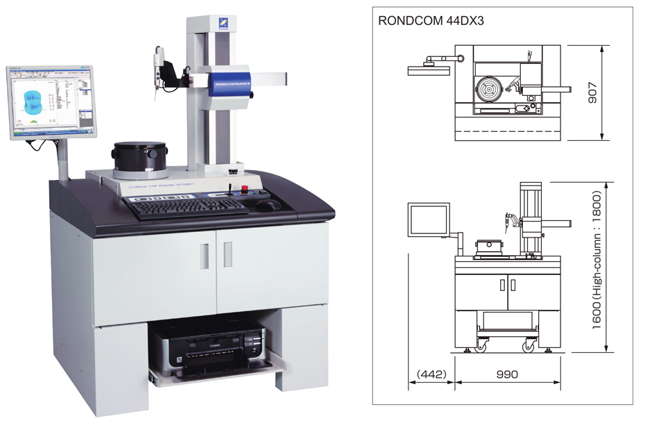
In precision manufacturing, roundness measuring machine calibration is essential for maintaining the accuracy of circular components. Ensuring that measurements meet stringent specifications depends on the proper adjustment and verification of these machines. While commonly referred to as “calibration,” the term is not entirely accurate in this context. Let’s explore how to optimize the performance of roundness measuring systems.

1. Key Components of a Roundness Measuring Machine Calibration System
A typical roundness measuring machine includes several crucial parts:
- Probe: The electronic sensor that detects motion.
- Stylus: The contact point that physically touches the part being measured.
- Spindle: The rotating component that moves the part or the sensor.
2. Tools for Successful Roundness Measuring Machine Calibration
- Precision Sphere/Hemisphere: A very round object used to test the instrument’s spindle.
- Flick/Dynamic Calibration Standard: A specimen with a very round area and a flat ground into it, used for adjusting probe gain.
- Optical Flat with Gage Blocks: Used to adjust probe gain by measuring step heights
3. Roundness Measuring Machine Calibration: Step-by-Step Guide
3.1. Adjusting the Probe Gain
3.1.1. Using a Flick/Dynamic Standard
- Center the Flick Standard: Carefully position the flick standard on the instrument, making sure to avoid the flat area while centering.
- Measure the Standard: Take a measurement of the standard using the roundness measuring machine.
- Scale the Measured Value: Using the instrument’s software, scale the measured value to match the certified value of the flick standard. This involves calculating and applying a gain correction factor. This adjustment is essential because different stylus lengths and contact angles impact sensitivity.
- Ensure the measuring instrument processes the data in the same manner as the specimen was calibrated.
- The flick standard method is generally easier and is useful for quick checks to confirm the system is providing expected roundness values.
3.1.2. Using Gage Blocks
- Level the Optical Flat: Ensure the optical flat is level before proceeding.
- Wring Gage Blocks: Attach two certified gage blocks to the optical flat, creating a step.
- Measure Height on First Block: Place the measuring stylus on one of the gage blocks and record the height.
- Measure Height on Second Block: Move the stylus to the other block and record the height difference between the two.
- Scale the Measured Height Difference: Adjust the system so the measured height difference matches the known height difference between the gage blocks.
- The gain-setting operation should isolate the probe/stylus combination and move it through a known displacement. The orientation is not as important as ensuring a stable configuration.
3.2. Checking Spindle Radial Accuracy
- Center the Hemisphere: Place the hemisphere on the instrument’s spindle, ensuring it’s accurately centered
- Take an Initial Measurement: Measure the hemisphere.
- Rotate the Hemisphere: Stop the spindle, remove the hemisphere, rotate it by a known angle, and re-center it.
- Take a Second Measurement: Measure the hemisphere again at the new angular position.
- Analyze Results: If errors rotate along with the hemisphere, they are part errors. If errors remain at the same angular position between measurements, they are errors in the spindle. This procedure is not used for calibrating the gain of the gauge/stylus combination.
3.3. Component Setup
- Kinematic Mounting: Use a three-point mounting system to ensure stability and prevent rocking of the component.
- Lateral Stability: Ensure that the component is stable laterally, especially for lighter parts.
- Centering: Use the instrument’s centering adjustments (X and Y) to align the component’s axis with the spindle axis. Start centering at the “null position”. The null position is the pivot point for the levelling adjusters and is the point where levelling has minimal effect on the component centring.
- Levelling: Position the stylus at the highest point on the component and use the leveling adjustments (A and B) to make the component axis parallel to the spindle axis. The centering and levelling planes should be as far apart as possible.
- Re-Center: After levelling, re-center the component at the null position to correct any residual centering error.
3.4. Addressing Component Eccentricity
- Use the formula: Expected Roundness (RONt) x Part Diameter (Ø)
- Use the provided graph to determine the acceptable eccentricity based on your calculation, aiming for a minimal error. For example, a part with a 50mm diameter and an expected roundness of 0.0001mm should be centered to no greater than 0.7µm to achieve less than 1% error due to eccentricity.
3.5. Regular Checks
By focusing on proper roundness measuring machine calibration, precision manufacturers can ensure consistent and accurate measurements. Regular adjustments, careful setup, and adherence to these calibration steps will significantly improve the machine’s performance and reliability.
