
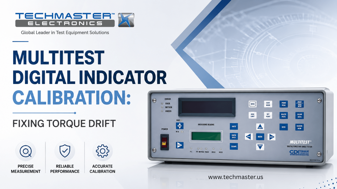
Multitest Digital Indicator Calibration…
Accuracy across the range
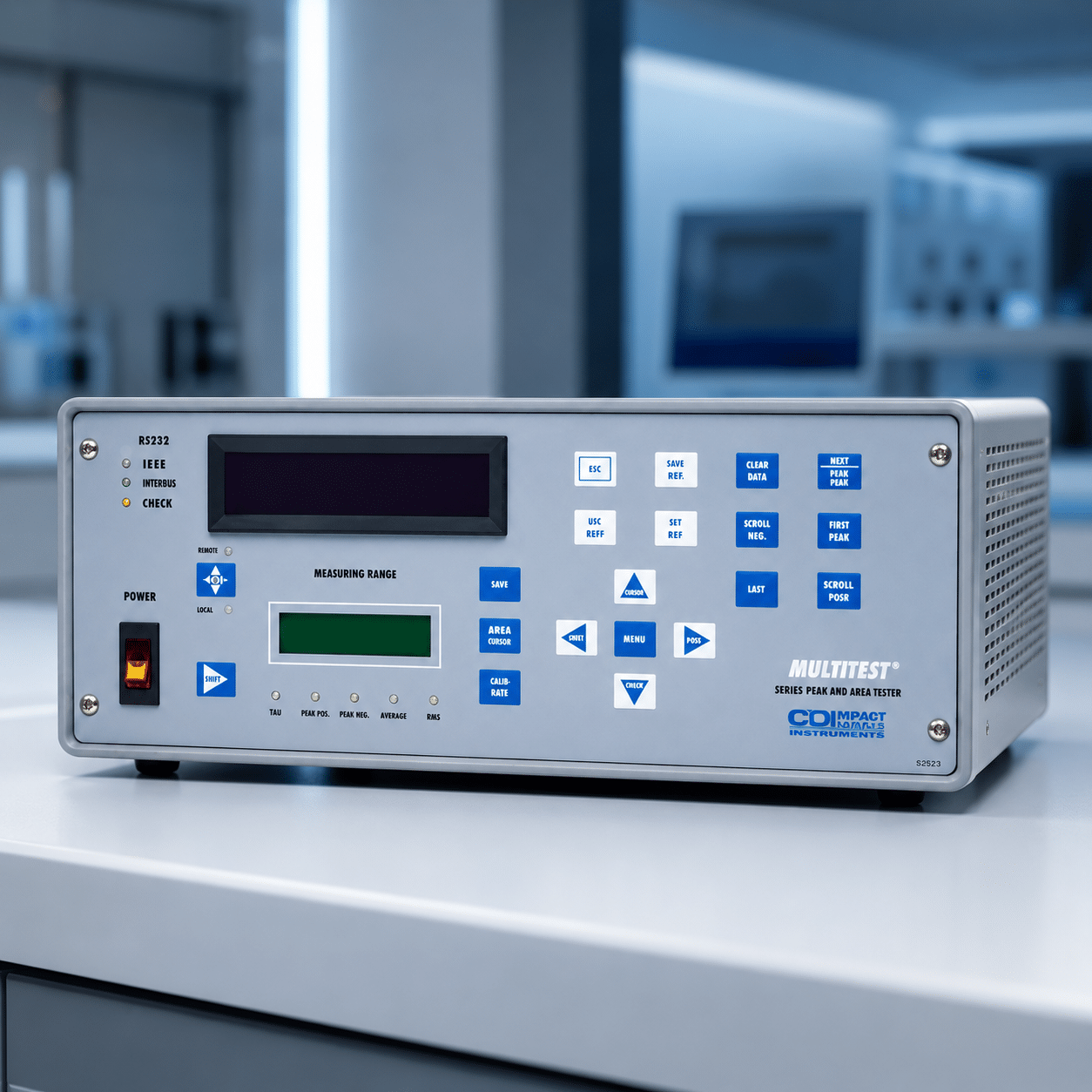
How Multitest Digital Indicator calibration works
- Intake & visual inspection
- Environmental stabilization
- As-found measurement
- Comparison to NIST-traceable standards
- Adjustment if required
- As-left results & certificate
Your calibration, covered
In-lab vs on-site calibration
In-lab calibration
- Accredited bench with full reference standards
- Best achievable measurement uncertainties
- Pickup & return logistics handled
- Ideal for precision and reference work
On-site calibration
- We calibrate the Multitest Digital Indicator at your facility
- No shipping risk or transit downtime
- As-found data captured before any move
- Ideal for fixed, large or sensitive assets
In-depth guide
Multitest Digital Indicator Calibration: Fixing Torque Drift
In aerospace, manufacturing, and mechanical maintenance, accurate torque control is critical for safety and product quality. Engineers use digital indicators with torque transducers to verify click wrenches, dial wrenches, and electronic drivers. Over time, temperature changes, electrical noise, and component aging cause signal drift and measurement errors. As a result, inaccurate torque readings can lead to loose joints, damaged bolts, and costly production issues. Routine multitest digital indicator calibration helps maintain accuracy, ensure traceability, and support reliable operation.
1. Technical Principles: Strain Gauge Amplification and Electronic Drift Mechanics
1.1. What are the fundamental engineering factors affecting digital torque display accuracy?
Multitest Digital Indicator Calibration is the specialized metrological evaluation and adjustment of a digital torque display using precise reference voltage sources. This process isolates and corrects errors within the analog-to-digital converter (ADC). Excitation voltage regulators, and non-linear microprocessor calculation algorithms.
1.2.Excitation Voltage Shifting and Instrumentation Amplifier Offsets
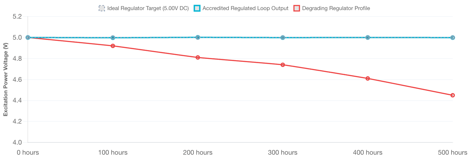
Torque transducers that use internal Wheatstone bridge strain gauges require a highly stable excitation voltage supplied directly by the digital indicator. If this internal reference power supply drifts by even a few millivolts due to component aging. The returned signal from the transducer shifts proportionally. Causing false readings.
Simultaneously, the internal instrumentation amplifier must boost the small microvolt signal from the sensor up to a usable volt level. Over time, internal semiconductor degradation creates small parasitic DC voltage offsets within this amplifier stage. Consequently, these electrical anomalies cause the screen to display a false torque reading even when the attached transducer is at rest under zero load. Professional calibration isolates the digital indicator from the physical sensor. Using a certified microvolt generator to identify and eliminate these internal amplifier errors.
1.3. ADC Non-Linearity and Stored Calibration Factor Decay
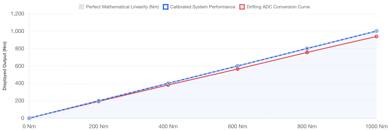
The analog-to-digital converter (ADC) inside the indicator is responsible for turning continuous analog voltage curves into digital bits for the microprocessor. However, as the ADC ages, its voltage-to-digital response curve can develop mathematical non-linearity near the upper and lower boundaries of its measurement span.
Furthermore, the digital display stores unique calibration factors (Cal Factors) for different transducer channels inside its non-volatile EEPROM memory. Sudden factory voltage surges or electrostatic discharges can degrade these saved bits over time, causing the internal processor to scale the incoming sensor data incorrectly. By performing multi-point electronic verification across the entire input range, metrologists recalculate the linear scaling curve and flash updated correction coefficients directly into the instrument’s firmware.
3. Industrial Applications: Where Display Accuracy Prevents Structural Failures
How does precise digital force display verification impact real-world manufacturing workflows?
Digital force display verification provides maintenance teams with a reliable data foundation to control industrial fastening tools. Maintaining absolute instrument accuracy prevents dangerous mechanical errors caused by both under-torquing and over-torquing critical fasteners.
-
Aerospace and Avionics Assembly: Tightening structural nuts on aircraft frames and jet engine casings requires incredibly tight torque tolerances. If the central digital display drifts and outputs incorrect data, the torque wrenches used for inspection will be set incorrectly, directly compromising flight safety.
-
Automotive Production Lines: Safety-critical joints, such as suspension mounts, brake calipers, and steering columns, depend on precise torque validation stations. Regular indicator calibration ensures automated assembly systems operate within engineering specifications, preventing expensive vehicle recalls.
-
Wind Turbine Maintenance: The massive bolts that secure wind turbine blades experience immense dynamic loads and require perfectly uniform tensioning. Accurate digital indicators help field technicians calibrate high-capacity hydraulic multipliers correctly, stopping structural bolt fatigue and catastrophic tower failures.
-
Medical Device Manufacturing: Orthopedic surgical tools and internal implants require micro-torque adjustments during production. Testing these tools with a calibrated digital indicator protects material integrity and ensures medical hardware complies with international healthcare safety laws.
4. The Calibration Pillar: Securing Traceability and ISO/IEC 17025 Compliance
ADC Non-Linearity Scaling Errors
Comparing linear output conversion accuracy between a calibrated indicator and a drifting unit across the measurement span.
Excitation Power Supply Stability over Time
Tracking output voltage fluctuations of a stable DC regulator vs. a degrading component experiencing thermal fatigue.
Why is traceable laboratory testing mandatory for industrial digital force indicators?
Traceable multitest digital indicator calibration connects factory-floor torque metrics directly to international standards through an unbroken chain of precision laboratory comparisons. This rigorous metrological oversight calculates measurement uncertainty, satisfies strict quality audits, and protects corporations from product liability claims.
Operating unverified digital displays introduces massive compliance and legal liabilities into a manufacturing facility. Because electronic drift happens slowly without showing clear hardware symptoms, the instrument fails silently, continuing to display numbers without throwing error codes. If a quality control team uses a drifting display to verify secondary assembly wrenches, a cascade of measurement errors spreads through the entire operation, invalidating data logs and triggering audit failures.
Implementing an ISO/IEC 17025 accredited calibration schedule thoroughly mitigates these operational risks. Certified metrologists test indicators using high-stability strain gauge simulators and reference multimeters that maintain direct traceability to the National Institute of Standards and Technology (NIST). This empirical review determines exact uncertainty parameters and issues an accredited calibration certificate. This formal documentation satisfies external quality auditors, confirms internal engineering metrics, and maintains production integrity.
5. How to Prepare a Digital Indicator for On-Site Calibration
Following this precise checklist ensures your industrial torque measurement instruments are structurally optimized for an upcoming field calibration session.
1. Inspect Input Ports and Clean Contact Pins
Examine the female transducer connection ports (such as DB9 or Amphenol jacks) for bent pins, cracked housings, or corrosion. Clean the internal contacts carefully using electrical contact cleaner and a lint-free micro-swab to eliminate parasitic resistance that can distort millivolt signals.
2. Verify Charging Cables and Shielding Integrity
Check the AC/DC power adapters and sensor cables for physical cracking, loose wires, or shielding tears. Intact cable shielding is mandatory because external electromagnetic noise from factory machinery can leak into unshielded lines, introducing signal noise into the data processor.
3. Implement Ambient Thermal Stabilization
Place the digital indicator inside the calibration laboratory environment for at least four hours before starting any technical measurements. This soaking period allows the sensitive internal semiconductors to reach complete thermal equilibrium with the room, neutralizing initial warm-up drift.
4. Document System Firmware and Clear Active Offsets
Record the instrument’s exact serial number, active firmware version, and memory configuration settings in your asset management database. Clear or document all user-defined calibration offsets and zero tares to ensure the metrologist can evaluate the equipment’s true “As-Found” baseline.
5. Techmaster US: Your Partner for Certified Instrument Calibration
Why Choose Techmaster US for Certified Equipment Calibration?
-
Full ISO/IEC 17025 Accreditation: Every technical procedure is executed under the strict quality governance of our ANAB cert AC-1736 framework.
-
Rapid On-Site Field Calibration: We deploy fully equipped mobile laboratories to verify your test systems directly at your production plant, minimizing asset downtime.
-
Comprehensive Metrological Scope: Our capabilities span advanced electronics, thermodynamics, dimensional parameters, and mechanical systems across your entire industrial footprint.
Frequently Asked Questions (FAQs)
1. What is the recommended frequency for multitest digital indicator calibration?
Multitest Digital Indicator Calibration must be performed at least once every twelve months to correct for the natural drift of internal analog circuits and reference amplifiers. However, if the device operates continuously across multiple shifts in high-vibration manufacturing zones, a six-month calibration cycle is highly recommended to protect data integrity.
2. How does a drop in excitation voltage affect torque measurement data?
When the internal power regulation circuits degrade, they can no longer maintain a steady excitation voltage to the external transducer. Because the millivolt output returned by the strain gauges is directly proportional to this input power, any drop in excitation voltage causes the display to show a torque value lower than the true applied force.
3. Can I calibrate a precision digital indicator using a standard mechanical torque wrench?
A standard mechanical wrench lacks the necessary resolution, accuracy, and stability to calibrate an electronic indicator. The calibration process requires specialized strain gauge simulators and reference multi-meters inside an accredited laboratory environment to verify the instrument’s electrical processing independent of mechanical variables.
4. What is the primary difference between Track and Peak Hold modes?
Track mode displays the real-time torque value continuously as force is applied and released from the connected transducer. In contrast, Peak Hold mode instantly captures and locks the highest torque value reached during the tightening cycle on the screen, allowing technicians to record peak data without it resetting when pressure stops.
5. Why is an ISO/IEC 17025 certificate required for factory quality audits?
An ISO/IEC 17025 certificate provides legally defensible proof that your test equipment was verified using audited metrological procedures and traceable national reference standards. This official documentation is mandatory for passing international quality audits, fulfilling client contracts, and removing regulatory compliance risks.
Frequently asked questions
What is Multitest Digital Indicator Calibration?
How often should a Multitest Digital Indicator be calibrated?
What standards apply to Multitest Digital Indicator Calibration?
What is included on the certificate?
Can you calibrate the Multitest Digital Indicator on-site?
Need Multitest Digital Indicator calibration?
ANAB-accredited, NIST-traceable, fast turnaround — in-lab or on-site across the USA.
Contact us for a quoteReferences & industry standards
- ISO/IEC 17025 testing & calibration laboratory requirements
- NIST calibration services and measurement traceability
- NIST Mass and Force Group
- A2LA / ANAB accreditation for calibration laboratories
External standards bodies. Techmaster Electronics is an ISO/IEC 17025-accredited, NIST-traceable calibration laboratory.

Khanh Nguyen is the Marketing Manager at Techmaster Electronics, a B2B marketing leader covering the test & measurement and ISO/IEC 17025 accredited calibration industry across the US and Vietnam markets.
