
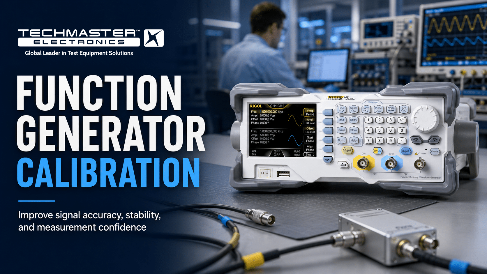
Function Generator Calibration
Frequency response at a glance
How Function Generator calibration works
- Intake & visual inspection
- Environmental stabilization
- As-found measurement
- Comparison to NIST-traceable standards
- Adjustment if required
- As-left results & certificate
Your calibration, covered
In-lab vs on-site calibration
In-lab calibration
- Accredited bench with full reference standards
- Best achievable measurement uncertainties
- Pickup & return logistics handled
- Ideal for precision and reference work
On-site calibration
- We calibrate the Function Generator at your facility
- No shipping risk or transit downtime
- As-found data captured before any move
- Ideal for fixed, large or sensitive assets
In-depth guide
Uncalibrated signal sources introduce severe measurement drift and hidden waveform distortion. Consequently, these issues trigger catastrophic compliance failures during critical industrial quality control testing. Furthermore, when your signal source deviates from nominal values, every subsequent test becomes invalid. As a result, this deviation costs thousands of dollars in rework and audit non-conformances. Therefore, you must establish absolute operational confidence. To achieve this, we recommend executing systematic, ISO 17025 accredited electrical calibration alongside structured waveform generator output verification on a strict schedule.
DEVICE OVERVIEW & INDUSTRIAL ROLE
A function generator is also widely configured as an arbitrary waveform generator (AWG). In practice, this indispensable piece of precision electronic test equipment generates repeatable electrical waveforms across a broad spectrum of frequencies. Specifically, these instruments utilize direct digital synthesis or advanced digital-to-analog conversion architectures to produce highly stable periodic signals. In addition, common output profiles include sine waves, square waves, triangular waves, ramp signals, and complex user-defined arbitrary patterns. In modern industrial environments, these precise waveforms serve as foundational reference inputs. For instance, engineers use them for testing amplifiers, medical devices, automotive sensors, and telecommunications infrastructure. Indeed, unexpected harmonic distortion, frequency deviation, or amplitude flatness errors create significant ambiguity. As a consequence, the test engineer cannot distinguish whether the device under test is faulty or if the source signal itself is degraded. Therefore, you must ensure the accuracy of these generators through verified calibration. Ultimately, this practice is paramount for maintaining global manufacturing standards and strict product reliability.FUNCTION GENERATOR CALIBRATION
Pre-requisites & Tools Needed for Function Generator Calibration
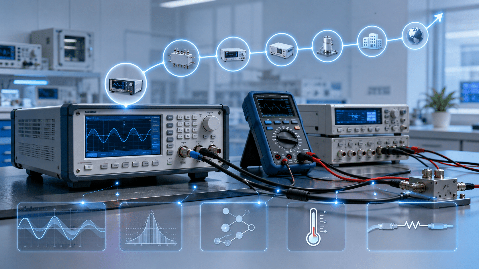
To perform a highly accurate calibration on these advanced instruments, you must establish a controlled metrology environment. In addition, you must utilize specific reference standards. The following list outlines the essential equipment required before commencing the procedure:- Primary Reference Standard: A high-precision digital multimeter (typically 8.5-digit resolution) with wideband alternating current voltage measurement capabilities.
- Frequency Standard: A rubidium frequency standard or a GPS-disciplined oscillator linked to the reference input of your measuring instruments.
- Measurement Receiver / Signal Analyzer: A calibrated spectrum analyzer or measuring receiver featuring exceptional harmonic analysis performance.
- High-Bandwidth Oscilloscope: A digital storage oscilloscope with sufficient analog bandwidth (typically 1 Gigahertz or higher) and flat frequency response.
- Cabling and Termination: High-quality double-shielded coaxial cables (50 Ohm characteristic impedance) alongside certified feedthrough termination loads.
- Environmental Monitoring: A calibrated thermo-hygrometer tracks ambient parameters. To maintain stability, the laboratory environment must remain at 23 degrees Celsius plus or minus 3 degrees Celsius. Furthermore, the relative humidity must stay below 60 percent.
Step-by-Step “How-To” Function Generator Calibration Guide
To successfully execute function generator calibration and comprehensive arbitrary waveform generator calibration, follow this systematic industry walkthrough:Step 1: Inspect the physical integrity and perform preliminary environmental stabilization
First, inspect the instrument under test for any obvious physical damage, loose connectors, or thermal obstruction. Clean the output ports using appropriate contact cleaner if oxidation is present. Afterward, power on the unit under test and all reference standards. Allow them to warm up for at least 30 minutes in the stabilized environmental chamber to eliminate thermal drift.Step 2: Establish common reference clock synchronization
To start, connect the reference 10 Megahertz frequency output from your atomic master clock directly to the external reference frequency input. Next, connect the same master clock reference to the frequency counter or spectrum analyzer to ensure a fully synchronized timebase across the entire test bench.Step 3: Conduct frequency accuracy and timebase verification
First, set the generator under test to output a pure sine wave at a standard reference frequency. For example, use a 10 Megahertz signal. Subsequently, connect the main output channel directly to the calibrated frequency counter utilizing a verified 50 Ohm coaxial cable. Finally, record the measured frequency on your data sheet. This confirms that the internal reference clock error falls within the specified manufacturer limits.Step 4: Perform amplitude accuracy and flatness verification
Next, configure the generator to produce a sine wave at a low reference frequency, typically 1 Kilohertz. Route the signal into the 8.5-digit digital multimeter. At the same time, ensure the input impedance of the meter is set to match the output impedance of the generator. Then, systematically vary the output voltage settings across the entire dynamic range while capturing the root-mean-square amplitude. After that, sweep the frequency across the active band to verify amplitude flatness.Step 5: Execute harmonic distortion and spectral purity verification
Subsequently, disconnect the generator from the multimeter. Then, route the output to the RF input of the calibrated spectrum analyzer. First, set the generator to output its maximum specified frequency sine wave. Next, adjust the analyzer to display the fundamental frequency along with its second, third, and fourth harmonics. Finally, measure the power levels of these harmonics relative to the fundamental carrier. This step verifies that the total harmonic distortion remains within acceptable metrological bounds.Step 6: Verify pulse characteristics and rise/fall time parameters
In addition, switch the generator output to a high-speed square wave with rapid transition times. Then, direct this signal into the high-bandwidth digital storage oscilloscope using proper impedance matching termination. Consequently, measure and document the rise time, fall time, overshoot, and duty cycle parameters to confirm waveform fidelity.Step 7: Record data and apply necessary firmware offsets
First, document all raw measurement values onto the official calibration datasheet. However, if any measured parameter deviates from standard limits, utilize manufacturer-specific adjustment software. This allows you to write new calibration constants directly to the internal non-volatile memory of the device.Traceability & Measurement Uncertainty in Function Generator Calibration
 Clearly, establishing an unbroken chain of traceability is the cornerstone of ISO 17025 accredited electrical calibration. Specifically, every measurement made during verification must trace back to national metrology institutes. For instance, we reference the National Institute of Standards and Technology. Furthermore, we preserve this traceability chain by calibrating our laboratory reference standards. This calibration occurs against higher-tier instruments on a strict, documented cycle.
To begin with, you must account for several critical uncertainty contributors systematically. In particular, the overall uncertainty budget includes the uncertainty of the reference digital multimeter. It also factors in the temperature coefficient of the test environment, interface repeatability, and cable loading effects. Consequently, you must combine these individual components using the root-sum-square method. This calculation determines the expanded measurement uncertainty. Typically, this expanded uncertainty is expressed with a coverage factor of two. As a result, this provides a confidence level of approximately 95 percent.
Clearly, establishing an unbroken chain of traceability is the cornerstone of ISO 17025 accredited electrical calibration. Specifically, every measurement made during verification must trace back to national metrology institutes. For instance, we reference the National Institute of Standards and Technology. Furthermore, we preserve this traceability chain by calibrating our laboratory reference standards. This calibration occurs against higher-tier instruments on a strict, documented cycle.
To begin with, you must account for several critical uncertainty contributors systematically. In particular, the overall uncertainty budget includes the uncertainty of the reference digital multimeter. It also factors in the temperature coefficient of the test environment, interface repeatability, and cable loading effects. Consequently, you must combine these individual components using the root-sum-square method. This calculation determines the expanded measurement uncertainty. Typically, this expanded uncertainty is expressed with a coverage factor of two. As a result, this provides a confidence level of approximately 95 percent.
Technical Compliance for Function Generator Calibration
Importantly, this rigorous calibration procedure complies fully with international quality management frameworks and metrological regulations. Specifically, this process satisfies the requirements of ISO/IEC 17025. This standard governs the general requirements for the competence of testing and calibration laboratories. Additionally, it fulfills the strict equipment control and traceability directives found in ANSI/NCSL Z540.3 and ISO 9001. By adhering strictly to these standards, facilities ensure their data is universally accepted. Consequently, this simplifies validation by global regulatory bodies during official quality audits.EXPERT ADVISORY
To ensure the long-term reliability of your wave-generating instruments between formal calibration cycles, you should implement a structured maintenance schedule. This proactive approach prevents unexpected downtime. Indeed, you must perform visual inspections of the output BNC connectors every month for major industrial models. Specifically, look for wear, physical deformation, or debris that could alter the 50 Ohm characteristic impedance. Furthermore, before connecting any generator to an active circuit, verify that there is no back-feed voltage or electrostatic discharge. This is crucial because reverse power can easily destroy the sensitive output driver stage. In addition, the environmental conditions under which these units are stored and operated dictate their long-term component stability. Specifically, the ideal storage temperature range is between 10 degrees Celsius and 40 degrees Celsius. Additionally, the non-condensing relative humidity must stay below 80 percent. During active laboratory operation, keep the ambient temperature regulated to 23 degrees Celsius plus or minus 2 degrees Celsius. Doing so significantly minimizes internal component drift. Consequently, this practice extends the duration for which the instrument remains within its certified accuracy specifications.MANDATORY TECHNICAL ASSETS
Prominent Models Function Generator Calibration Reference Table
The following reference table presents the standard models found throughout the global test and measurement industry, mapping them to their primary uses and governing calibration guidelines.| Manufacturer | Model | Typical Industrial Application | Applicable Calibration Standard |
|---|---|---|---|
| Keysight Technologies | 33612A | Automotive Sensor Emulation & R&D | ISO/IEC 17025 / ANSI/NCSL Z540.3 |
| Tektronix | AFG31022 | Aerospace & Defense Signal Testing | ISO/IEC 17025 / EURAMET cg-15 |
| Rohde & Schwarz | HMF2550 | Industrial Electronics Component Testing | ISO/IEC 17025 / VDI/VDE/DGQ/DKD 2622 |
| Rigol Technologies | DG4162 | Educational Labs & General Prototyping | ISO/IEC 17025 / Manufacturer Standard |
Definition Blocks for Signal Standards
The following core metrological definitions are essential for understanding the parameters verified during signal source calibration:Arbitrary Waveform Fidelity: The measure of how closely a generated electrical signal matches the mathematically defined or pre-programmed digital waveform shape, accounting for losses, distortion, and rise-time limitations in the analog output stage.
Spectral Purity: A technical term defining the absence of unwanted spectral components, such as harmonic distortion, non-harmonic spurious signals, and phase noise, relative to the desired fundamental output frequency of a signal source.
FAQ
1. What is the recommended calibration interval for the Keysight 33612A?
The recommended calibration interval for the Keysight 33612A is 12 months under standard laboratory usage. This annual cycle is technically justified by the manufacturer’s long-term stability specifications for the internal voltage references and quartz crystal timebase, which can experience measurable drift over a 365-day operating period.2. Why does my arbitrary waveform generator show amplitude errors at high frequencies?
Your arbitrary waveform generator shows amplitude errors due to high-frequency attenuation, cabling losses, and impedance mismatches. As frequency increases, cable capacitance and the high-frequency response of the output amplifiers cause natural signal roll-off, requiring specialized waveform generator output verification to correct these transmission path errors.3. Is ISO 17025 accredited electrical calibration necessary for consumer-grade function generators?
Yes, ISO 17025 accredited electrical calibration is highly necessary if the instrument is utilized in any certified testing or medical manufacturing capacity. Without this accredited calibration, the measurements lack formal traceability, rendering your testing data legally invalid and non-compliant with international regulatory authorities.4. How does temperature affect the frequency accuracy of a waveform generator?
Temperature changes directly affect the resonant frequency of the internal reference oscillator, causing the timebase to drift. Utilizing a highly stable temperature-compensated crystal oscillator or linking the generator to an external rubidium frequency standard mitigates this thermal drift during critical test procedures.5. What is the difference between standard function generator calibration and arbitrary waveform generator calibration?
Standard calibration focuses primarily on fixed wave shapes like sine and square waves at specific frequencies. In contrast, arbitrary calibration requires additional verification of the digital-to-analog converter performance, vertical resolution, sample rate accuracy, and complex custom pattern reconstruction capabilities.CONCLUSION
To begin with, maintaining the precision of your test bench is non-negotiable for delivering reliable products and passing strict regulatory audits. Indeed, regular function generator calibration prevents measurement errors and minimizes production downtime. Furthermore, it guarantees that your development processes remain fully compliant with modern quality standards. If your equipment is due for its periodic verification, protect your testing integrity by contacting our certified laboratory today. Let our metrology specialists provide you with highly precise, traceable calibration services. Ultimately, this keeps your electronic instruments performing perfectly.Frequently asked questions
What is Function Generator Calibration?
How often should a Function Generator be calibrated?
What standards apply to Function Generator Calibration?
What is included on the certificate?
Can you calibrate the Function Generator on-site?
Need Function Generator calibration?
ANAB-accredited, NIST-traceable, fast turnaround — in-lab or on-site across the USA.
Contact us for a quoteReferences & industry standards
- ISO/IEC 17025 testing & calibration laboratory requirements
- NIST calibration services and measurement traceability
- A2LA / ANAB accreditation for calibration laboratories
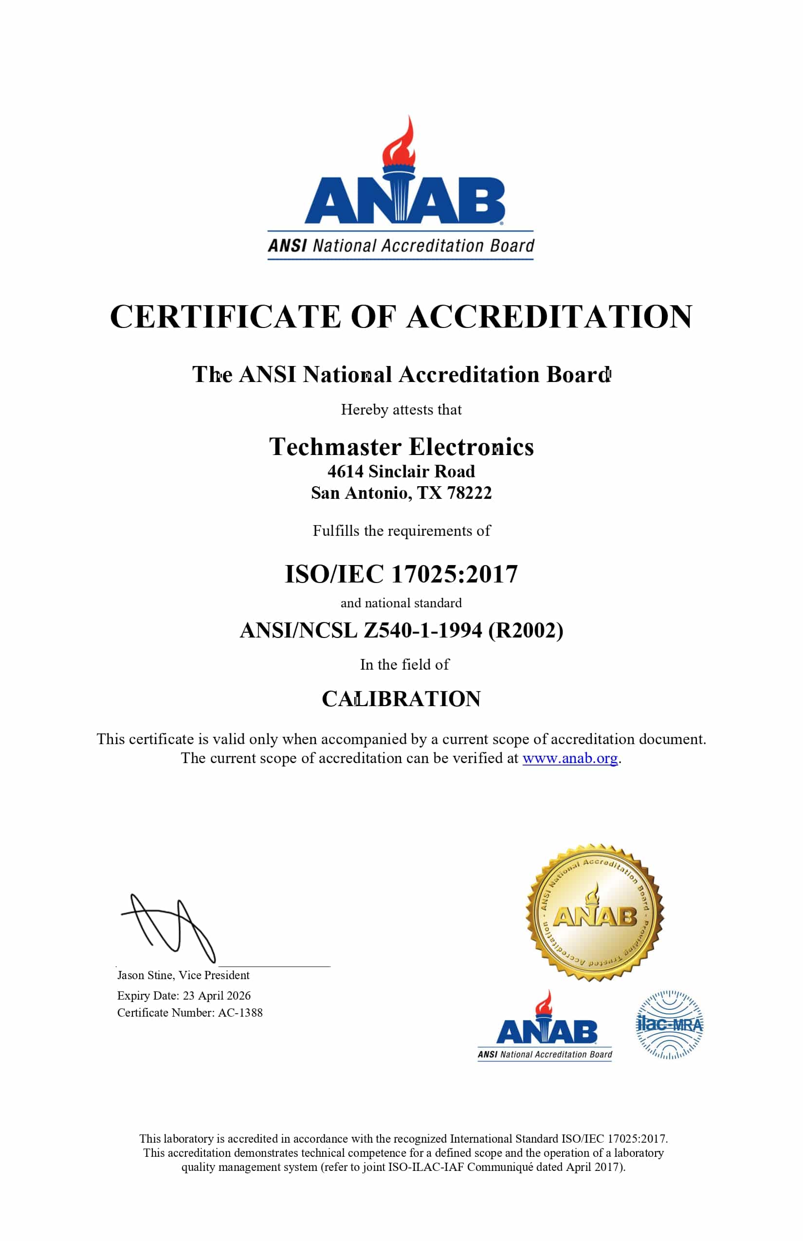
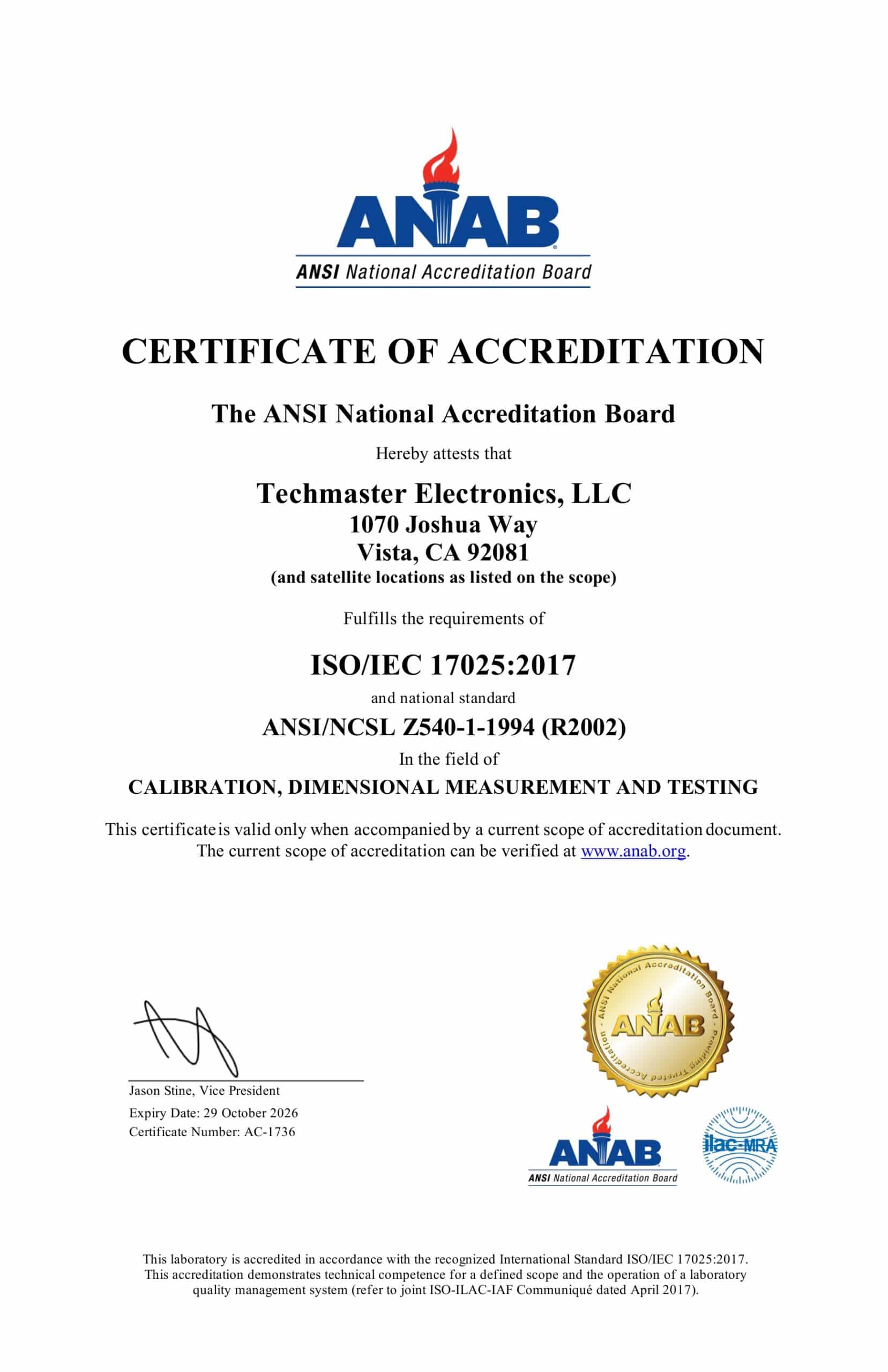
External standards bodies. Techmaster Electronics is an ISO/IEC 17025-accredited, NIST-traceable calibration laboratory.
Related reading: Allan deviation explained: measuring oscillator and frequency-standard stability

Khanh Nguyen is the Marketing Manager at Techmaster Electronics, a B2B marketing leader covering the test & measurement and ISO/IEC 17025 accredited calibration industry across the US and Vietnam markets.
