
Milli-Ohmeter Calibration
Accuracy across the range
How Milli-Ohmeter calibration works
- Intake & visual inspection
- Environmental stabilization
- As-found measurement
- Comparison to NIST-traceable standards
- Adjustment if required
- As-left results & certificate
Your calibration, covered
In-lab vs on-site calibration
In-lab calibration
- Accredited bench with full reference standards
- Best achievable measurement uncertainties
- Pickup & return logistics handled
- Ideal for precision and reference work
On-site calibration
- We calibrate the Milli-Ohmeter at your facility
- No shipping risk or transit downtime
- As-found data captured before any move
- Ideal for fixed, large or sensitive assets
In-depth guide
Milli-Ohmeter Calibration: Overcoming Low-Resistance Test Lead Drift
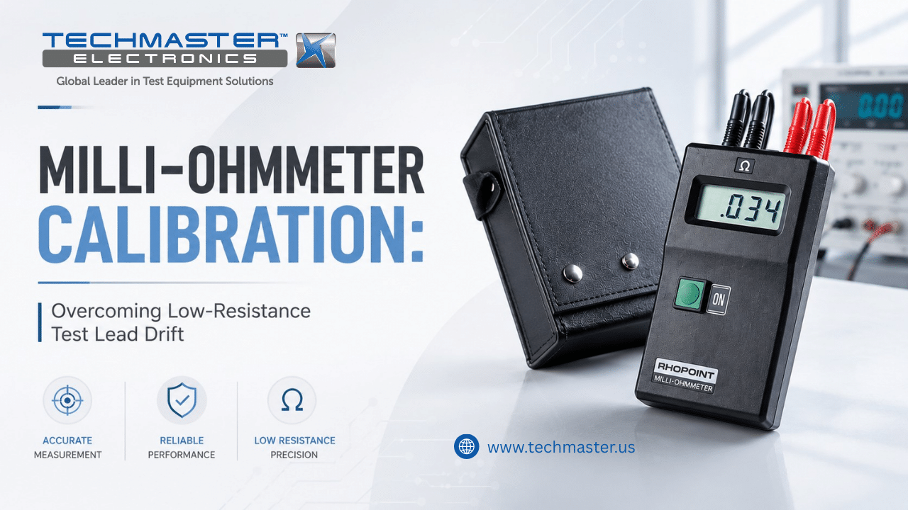
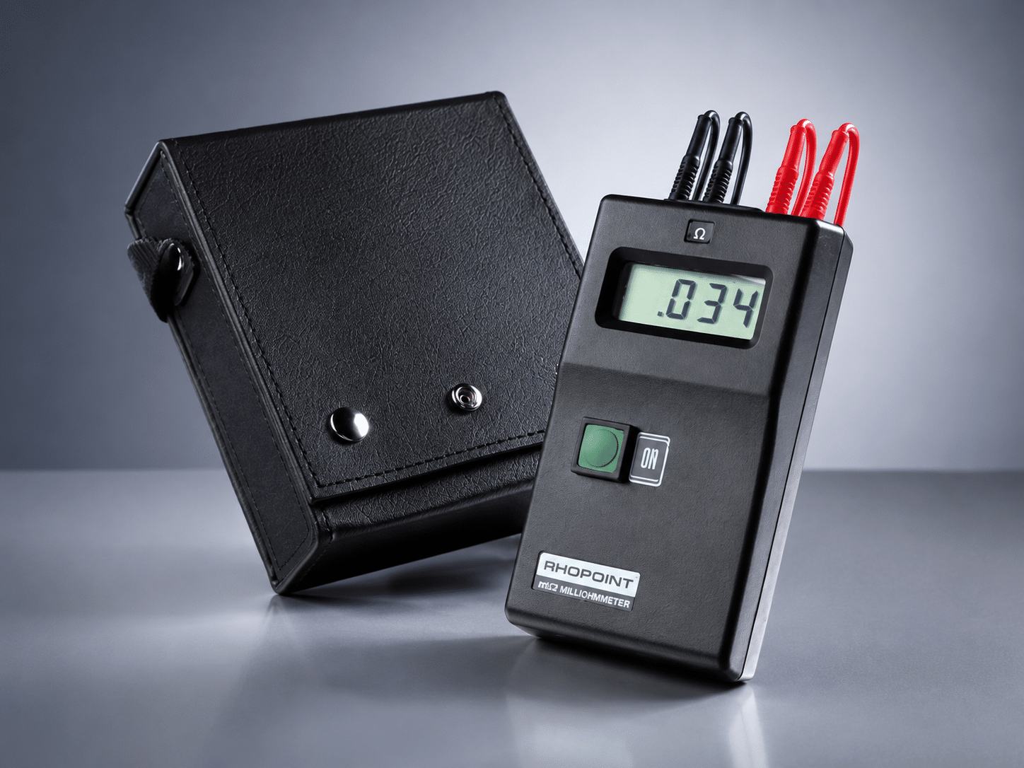
Accurate low-resistance measurement is essential in electrical manufacturing, aerospace systems, and EV battery production. High-precision instruments like the Rhopoint M210 are used to test transformer windings, ground bonds. And PCB traces at micro-ohm levels to detect hidden defects before products reach the market. Over time, temperature changes and continuous use can cause current-source drift, amplifier aging. And contact resistance issues, reducing measurement accuracy. Without regular milli-ohmeter calibration. These errors may go unnoticed. Leading to overheating, product failures, and failed quality audits. Accredited Milli-Ohmeter calibration ensures reliable measurements, traceability, and consistent production quality.
1. Technical Principles: Kelvin Connections and Thermal EMF Drift Dynamics
1.1. What are the fundamental engineering factors affecting ultra-low resistance accuracy?
Milli-Ohmeter Calibration is the specialized metrological testing. Adjustment of a low-resistance display against traceable standard resistors. This process corrects for constant-current source fluctuations, internal offset voltages. And test lead resistance anomalies across the device’s operational range.
1.2. Eliminating Lead Resistance via Four-Wire Kelvin Verification
Standard two-wire resistance configurations introduce significant errors. Because the meter inadvertently adds the physical resistance of the test leads directly into the measurement equation. To bypass this barrier. Precision milli-ohmmeters utilize a four-wire Kelvin connection system. This method employs two independent loops: one pair of wires forces a highly regulated current through the target resistor. While a second high-impedance pair measures the exact voltage drop directly at the component boundary.
Over months of active operation, the internal current-source regulators experience performance drift. Outputting slightly erratic currents. Furthermore, micro-corrosion inside the instrument input jacks adds parasitic resistance to the voltage sensing loop. Which tricks the internal processors. Metrologists resolve these structural errors by connecting the meter to ultra-stable, gold-plated four-terminal standard resistors, isolating and correcting the amplifier scaling parameters.
1.3. Thermal Electromotive Force (EMF) Offset Interferences
When two dissimilar metals connect within an electronic circuit, subtle temperature variations across the junctions create tiny parasitic voltages known as thermal EMF. Because milli-ohmmeters process exceptionally low voltage drops to compute micro-ohm values, even a fraction of a microvolt of thermal EMF can warp the final calculation significantly.
To combat this anomaly, advanced meters cycle their test current or apply pulsed DC configurations to calculate and mathematically subtract ambient thermal offsets. However, internal switching components age unevenly, causing this active filtering loop to degrade over time. Professional calibration tracks these microvolt shifts across both forward and reverse current cycles, updating the instrument firmware to maintain steady zero-point accuracy under fluctuating field temperatures.
2. Industrial Applications: Where Micro-Ohm Precision Protects Systems
How does precise low-resistance verification impact modern manufacturing and energy sectors?
Low-resistance verification provides engineering teams with the accurate baseline data needed to confirm structural and electrical integrity. Maintaining this strict measurement precision prevents overheating hazards, equipment dropouts, and catastrophic component fires.
-
Electric Vehicle Battery Pack Assembly: EV batteries use robust copper busbars welded together to transfer massive amounts of current between cell modules. If an uncalibrated meter accepts a high-resistance weld joint, that hidden bottleneck will generate localized heat spikes during acceleration, potentially melting cells and triggering battery fires.
-
Aerospace Lightning Protection Systems: Aircraft structures require highly conductive ground-strapping networks to safely redirect lightning strikes away from sensitive cockpit avionics. Regular meter testing ensures that every structural bond maintains an ultra-low resistance pathway, protecting flight systems from high-voltage energy surges.
-
Medical Diagnostic Instrumentation: Magnetic resonance imaging (MRI) units utilize large superconducting magnets wrapped in high-purity copper windings. Precise low-resistance tracking keeps these cooling and electrical pathways operating safely within spec, preventing dangerous system quenches and preserving expensive imaging components.
-
Printed Circuit Board (PCB) Quality Control: Multi-layer circuit boards route high-current paths through tiny copper vias that connect different layers. Accurate milli-ohm validation checks the consistency of these copper platings during production, helping engineers spot structural cracks or thin spots before boards enter the assembly stage.
3. The Calibration Pillar: Securing Traceability and ISO/IEC 17025 Compliance
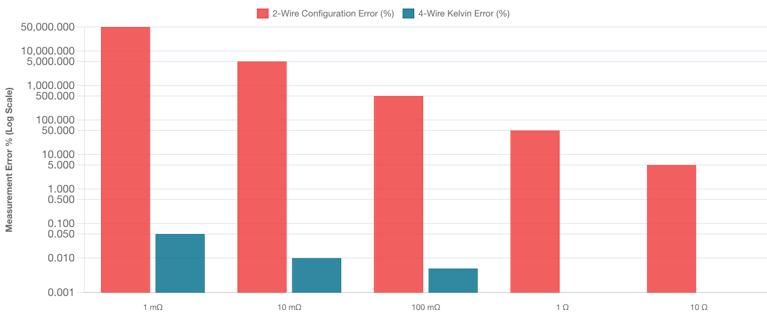
Error Comparison: 2-Wire Configuration vs. 4-Wire Kelvin Method
Tracking calculated percentage error across nominal resistance values. Note the catastrophic failure of 2-wire setups in the milli-ohm regime.
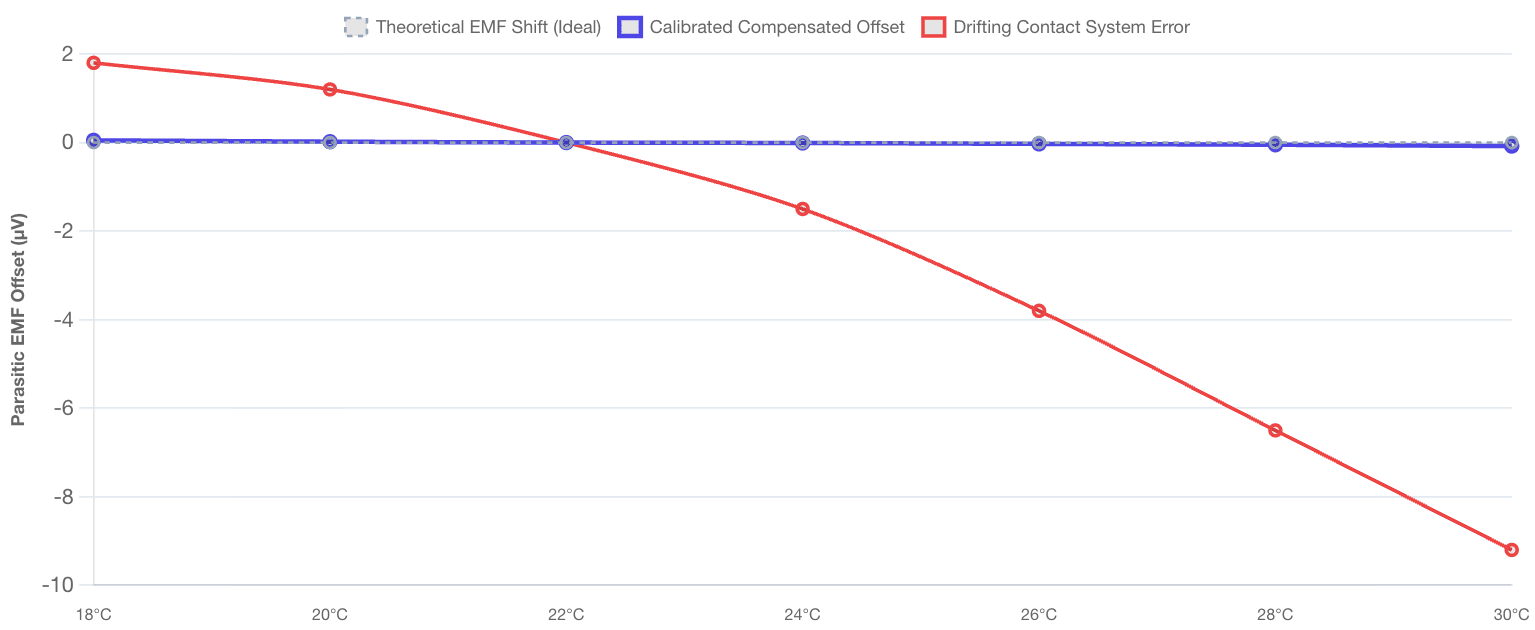
Thermal EMF Voltage Drift Profile (Laboratory Swings)
Illustrating parasite offsets at connector boundaries comparing uncalibrated systems to active temperature-compensated filters.
Why is traceable metrological testing mandatory for low-resistance laboratory assets?
Traceable milli-ohmeter calibration links shop-floor electrical measurements directly to global measurement frameworks through an unbroken chain of laboratory comparisons. This systematic approach defines exact measurement uncertainty boundaries, fulfills regulatory benchmarks, and defends production facilities against liability claims.
Operating low-resistance instrumentation without certified metrological oversight introduces severe quality control and compliance risks into a manufacturing workflow. Because internal circuit drift accumulates slowly without showing clear mechanical symptoms, a failing meter will continue to log stable readings that appear correct on the screen. If a maintenance engineer relies on a drifting reference standard to verify secondary production testers, a cascade of false-pass results spreads through the plant, invalidating quality records and setting up future field failures.
Adhering to an ISO/IEC 17025 accredited calibration cycle thoroughly eliminates these systemic production risks. Certified metrologists verify low-resistance instruments using high-stability laboratory shunts and reference multi-meters that maintain direct traceability to the National Institute of Standards and Technology (NIST). This empirical process calculates exact device uncertainties and generates an official calibration certificate. This formal document satisfies external quality auditors, confirms engineering parameters, and validates your manufacturing integrity.
4. How to Prepare a Milli-Ohmmeter for On-Site Calibration
Following this checklist helps prepare your low-resistance instruments for a successful field calibration session.
4.1. Clean All Four Input Terminals
First, check the binding posts, banana jacks, or BNC terminals for dust, grease, or oxidation. Then, clean the contact points with isopropyl alcohol and a lint-free swab. As a result, you can ensure a stable metal-to-metal connection during testing.
4.2. Check Kelvin Clips and Test Leads
Next, inspect the four-wire test leads and Kelvin clips for wear, loose jaws, or damaged insulation. In particular, frayed cables can affect loop resistance and allow electrical noise to interfere with sensitive readings. Therefore, replacing damaged leads helps maintain accurate calibration results.
4.3. Allow Time for Temperature Stabilization
Before calibration begins, place the milli-ohmmeter and test leads in the calibration room for at least four hours. This step allows the internal components to match the room temperature. Consequently, it reduces warm-up drift and improves measurement stability.
4.4. Record Settings and Clear Offsets
Finally, document the instrument serial number, firmware version, and current settings in your maintenance records. In addition, clear any stored lead compensation or user offsets. This allows the calibration technician to measure the instrument’s true baseline performance.5. Techmaster US: Your Partner for Certified Instrument Calibration
Why Choose Techmaster US for Certified Equipment Calibration?
-
Full ISO/IEC 17025 Accreditation: Every technical procedure is executed under the strict quality governance of our ANAB cert AC-1736 framework.
-
Rapid On-Site Field Calibration: We deploy fully equipped mobile laboratories to verify your low-resistance test systems directly at your production plant, minimizing asset downtime.
-
Comprehensive Metrological Scope: Our capabilities span advanced electronics, thermodynamics, dimensional parameters, and mechanical systems across your entire industrial footprint.
Do not allow unverified circuit drift or test port wear to compromise your low-resistance data or jeopardize your compliance standing. Contact Techmaster US today to receive an expert technical quote tailored to your facility’s unique instrument requirements.
Frequently Asked Questions (FAQs)
1. What is the recommended frequency for milli-ohmmeter calibration?
Milli-Ohmeter Calibration must be performed at least once every twelve months to counteract the natural drift of internal constant-current regulators and analog amplifiers. However, if the instrument is integrated into an automated production line or used daily to check heavy battery busbars, a six-month calibration interval is recommended to protect data logs.
2. Why can’t a standard two-wire multimeter check ultra-low resistances accurately?
A standard multimeter sends current and reads voltage along the same pair of test leads, meaning it counts the physical resistance of the leads and terminals as part of the measurement. When tracking micro-ohms, this extra wire resistance can be several ohms higher than the component value, completely distorting the readout.
3. How does thermal EMF skew low-resistance measurement values?
Thermal EMF develops when temperature differences across metal-to-metal junctions create small parasitic voltages along the analog signal path. Because milli-ohmmeters measure tiny microvolt drops to calculate resistance, these extra thermal voltages add an artificial bias that makes the displayed resistance read higher or lower than its true value.
4. What are the primary indicators that a milli-ohmmeter requires immediate calibration?
An instrument needs prompt metrological service if you notice drifting zero balances, erratic display fluctuations while clamping stable components, or a failure to null out lead resistance during setup. Physical oxidation or loose connection jacks at the terminal port also signal that a complete recalibration is necessary.
5. Why is an ISO/IEC 17025 accredited certificate critical for automotive battery production?
An ISO/IEC 17025 certificate provides legally defensible proof that your low-resistance testing equipment matches national standards through a verified chain of comparisons. This high-level documentation is mandatory for clearing international automotive safety audits, passing manufacturing quality reviews, and lowering product liability risks.
Frequently asked questions
What is Milli-Ohmeter Calibration?
How often should a Milli-Ohmeter be calibrated?
What standards apply to Milli-Ohmeter Calibration?
What is included on the certificate?
Can you calibrate the Milli-Ohmeter on-site?
Need Milli-Ohmeter calibration?
ANAB-accredited, NIST-traceable, fast turnaround — in-lab or on-site across the USA.
Contact us for a quoteReferences & industry standards
- ISO/IEC 17025 testing & calibration laboratory requirements
- NIST calibration services and measurement traceability
- A2LA / ANAB accreditation for calibration laboratories
External standards bodies. Techmaster Electronics is an ISO/IEC 17025-accredited, NIST-traceable calibration laboratory.

Calibration engineer at Techmaster Electronics, ISO/IEC 17025 accredited laboratory with 35+ years of metrology expertise.
