

Ask any seasoned metrologist why the calibration lab feels like a climate-controlled vault and you will get the same answer: the environment is part of the measurement. A gauge block, an oscilloscope, a load cell, and an RF power sensor all read differently at 18 °C than at 26 °C. If the lab does not control and record its surroundings, the numbers on the certificate cannot be trusted, and an ISO/IEC 17025 assessor will say so. This guide explains the physics, the standards, the real limits Techmaster holds, and how ambient conditions flow into a defensible uncertainty statement.
Why do calibration labs control temperature and humidity?
Measurement is comparison, and comparison assumes stability. When the reference standard and the unit under test sit at different temperatures, or when either is drifting, the comparison captures thermal noise instead of the true value. In dimensional work the effect is mechanical, metals grow and shrink. In electrical and RF work it is subtler, resistor values, oscillator frequency, and connector geometry all move with temperature, and humidity changes leakage and contact resistance. A lab that ignores this does not just risk a fuzzy number; it risks a wrong in-tolerance or out-of-tolerance decision that ripples out to every instrument it touched.
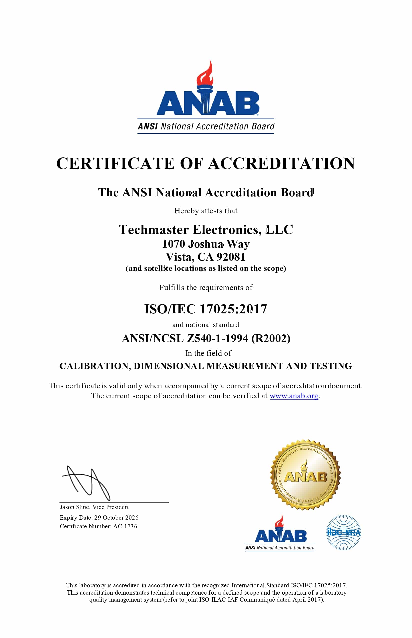
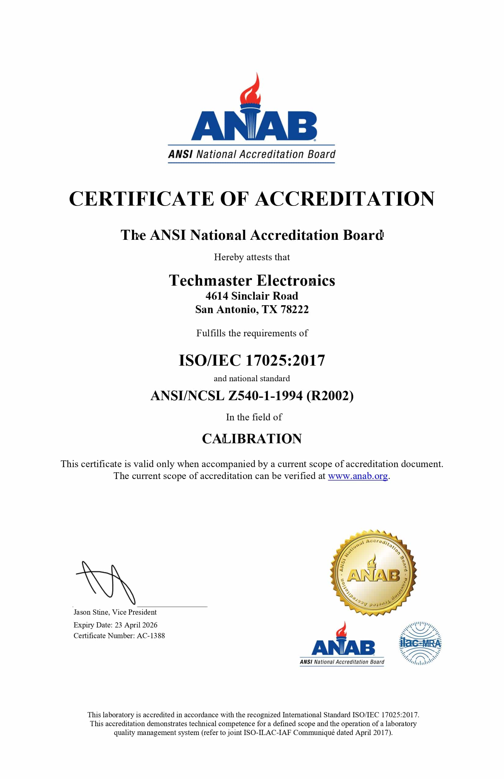
Techmaster Electronics has run ISO/IEC 17025 accredited calibration laboratory operations since 1989 (ANAB Cert. AC-1736), and across a 10-year, 381,916-calibration dataset the single most common cause of borderline as-found data is not instrument failure, it is measurement performed before the item reached thermal equilibrium with the lab.
What is the 20 °C standard reference temperature, and why does it matter?
The 20 °C convention exists so that a part measured in California, Texas, or Germany means the same thing everywhere. ISO 1:2022 makes an important clarification that trips up many quality teams: neither the part nor the instrument has to physically sit at exactly 20 °C during measurement, but the consequence of not being at 20 °C must be included in the measurement uncertainty. That is why dimensional labs cluster their environment tightly around 20 °C, it keeps the temperature correction (and its uncertainty) small enough to ignore or easily bound. Electrical and RF disciplines commonly use a 23 °C nominal instead, reflecting the reference conditions on many instrument datasheets.
How does temperature affect measurement results?
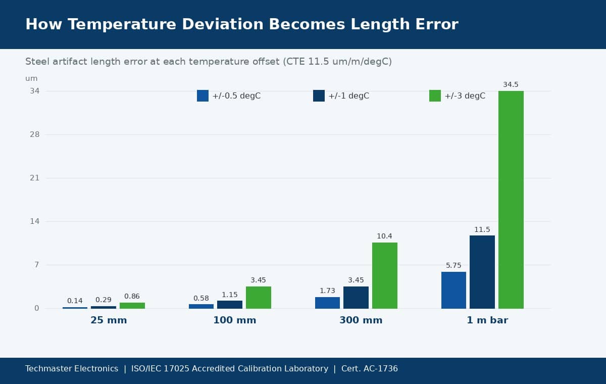
For dimensional metrology the driver is the coefficient of thermal expansion (CTE). Steel expands roughly 11.5 µm per meter per °C; aluminum nearly double that. The table below shows how a modest temperature offset turns into real length error on common steel artifacts, the reason coordinate measuring machines live in tightly held rooms (see our CMM calibration guide).
| Steel artifact length | Error at ±0.5 °C | Error at ±1 °C | Error at ±3 °C |
|---|---|---|---|
| 25 mm gauge block | 0.14 µm | 0.29 µm | 0.86 µm |
| 100 mm gauge block | 0.58 µm | 1.15 µm | 3.45 µm |
| 300 mm scale | 1.73 µm | 3.45 µm | 10.4 µm |
| 1 m length bar | 5.75 µm | 11.5 µm | 34.5 µm |
Based on a steel CTE of 11.5 µm/m/°C. Actual CTE varies by alloy; the point is that error scales with both length and temperature deviation.
In the electrical and RF disciplines the mechanism differs but the lesson is identical. Precision resistors and voltage references carry a temperature coefficient (often a few ppm/°C); crystal oscillators and rubidium references specify frequency vs temperature; and connector dimensions in microwave work shift enough to matter at high frequency. A 23 °C ±2 °C envelope keeps these contributions inside the datasheet reference conditions so the standard performs to its published spec.
How does humidity affect calibration?
High relative humidity is the enemy of high-impedance and RF measurement: moisture films create leakage paths that corrupt insulation-resistance, teraohm, and low-current work, and it accelerates corrosion of the precision connectors that RF and microwave standards depend on. Low humidity is equally dangerous in a different way, dry air lets static charge build, and a single ESD event can silently shift or destroy a sensitive front end. Hygroscopic materials (some plastics, certain reference artifacts, and desiccant-sensitive sensors) also change dimension or behavior with moisture uptake. Holding humidity in a stable band is therefore about protecting equipment life as much as data quality.
What temperature and humidity limits should a calibration lab hold?
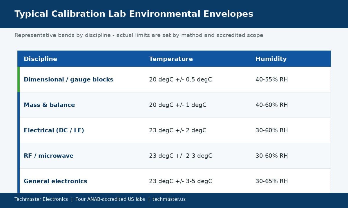
ISO/IEC 17025 does not dictate a universal setpoint. Instead it requires that environmental requirements be defined by the methods in use and then met. The values below reflect widely used industry practice and the kind of envelopes Techmaster maintains across its four ANAB-accredited laboratories (Vista CA, Santa Clara CA, Orlando FL, and San Antonio TX). Treat them as typical, not mandatory, your accredited scope and method define your actual limits.
| Discipline | Typical temperature | Typical humidity | Why it is tight or loose |
|---|---|---|---|
| Dimensional / gauge blocks | 20 °C ±0.5 °C | 40–55% RH | Thermal expansion dominates; tight control keeps length error sub-micron |
| Mass & balance | 20 °C ±1 °C | 40–60% RH | Air density and convection currents affect weighing |
| Electrical (DC/LF) | 23 °C ±2 °C | 30–60% RH | Component tempco and leakage; matches datasheet reference conditions |
| RF / microwave | 23 °C ±2–3 °C | 30–60% RH | Connector geometry and reference stability; corrosion control |
| General electronics | 23 °C ±3–5 °C | 30–65% RH | Looser tolerances tolerate a wider band |
What is thermal stabilization (soak time) and how long does it take?
Soak time is the most under-appreciated environmental control because it is invisible on the certificate yet decisive in the data. An item that arrives from a cold truck can be many degrees off lab temperature; measuring it immediately captures that offset as error. Rule-of-thumb soak times scale with thermal mass: small electronic instruments often need 1–4 hours of warm-up plus equilibration, precision dimensional artifacts commonly need overnight, and large steel or granite masses can need a full day. This is also why reputable labs record the ambient conditions at the time of measurement, a detail you can look for when you read an ISO/IEC 17025 calibration certificate.
How do environmental conditions enter the measurement uncertainty budget?
Environmental effects are not hand-waved away, they are quantified. For a dimensional measurement, the analyst multiplies the temperature deviation and its uncertainty by the artifact’s CTE and length to get a length-uncertainty contribution. For an electrical measurement, the temperature coefficient of the standard times the temperature band gives a voltage or resistance contribution. These terms sit in the budget alongside the reference standard, resolution, and repeatability, and they are combined using the standard GUM approach explained in our measurement uncertainty budget guide. A tighter environment shrinks these terms, which is precisely how a lab earns a smaller, more competitive calibration and measurement capability (CMC).
Key takeaways
- The environment is part of the measurement: temperature and humidity directly add error to calibration results.
- 20 °C (ISO 1:2022) is the reference temperature for dimensional work; electrical/RF often use a 23 °C nominal.
- A 1 °C error on a 100 mm steel block is ~1.15 µm, small offsets become real failures.
- Keep humidity roughly 30–60% RH to avoid static (too dry) and corrosion/leakage (too humid).
- Always allow soak time so the item reaches equilibrium before measurement.
- ISO/IEC 17025 clause 6.3 requires labs to monitor, control, and record conditions and to stop work when they compromise results.
How should a calibration lab monitor and record environmental conditions?
A compliant program has four parts: defined requirements (from each method), continuous monitoring with calibrated sensors, control systems (HVAC, humidification/dehumidification, airlocks) that keep the band, and records that prove it. Crucially, ISO/IEC 17025:2017 clause 6.3 also requires the lab to stop testing or calibration when conditions fall outside limits, a rule assessors actively check. The environmental sensors themselves must be traceable, and the whole framework ties back to the metrological traceability and ANAB accreditation that make the results defensible. NIST’s own dimensional-metrology work highlights why: as the NIST review of the 2016 ISO 1 revision notes, temperature is the dominant environmental influence on precise dimensional measurement.
The broader point for quality managers evaluating a supplier: a lab’s environmental discipline is a proxy for its overall rigor. If you want to see how these controls fit into a full accredited service, start with our ISO/IEC 17025 calibration services overview, and note that the same thermal care governs temperature-sensitive work such as thermocouple calibration.
Frequently asked questions
Does my whole factory need to be at 20 °C for calibration to be valid?
No. Only the calibration environment and the measurement itself need to meet the method’s requirements. ISO 1:2022 allows measurement away from 20 °C provided the temperature deviation is corrected and its uncertainty is included in the budget. On-site calibrations use documented ambient conditions and larger uncertainties when tight control is impractical.
What temperature and humidity does Techmaster hold in its labs?
Envelopes are discipline-specific: dimensional work is held near 20 °C ±0.5 °C, while electrical and RF disciplines typically use 23 °C ±2–3 °C with humidity between 30% and 60% RH. Each of the four ANAB-accredited Techmaster labs (Vista and Santa Clara CA, Orlando FL, San Antonio TX) monitors and records conditions continuously under Cert. AC-1736.
How long should an instrument soak before calibration?
It depends on thermal mass. Small handheld instruments often need 1–4 hours; precision dimensional artifacts commonly need overnight; large steel or granite masses can need 24 hours or more. The goal is thermal equilibrium with the lab, measuring before that captures the shipping temperature offset as measurement error.
Why is very low humidity a problem if it prevents corrosion?
Because dry air promotes electrostatic discharge. Below roughly 30% RH, static charge builds easily and a single ESD event can shift or destroy sensitive electronic front ends. The aim is a stable middle band, typically 30–60% RH, that avoids both static (too dry) and corrosion or leakage currents (too humid).
Does controlling the environment reduce my calibration uncertainty?
Yes. A tighter, well-recorded environment shrinks the temperature and humidity terms in the uncertainty budget, which lowers the expanded uncertainty and supports a smaller calibration and measurement capability (CMC). That is one reason accredited labs invest heavily in HVAC and monitoring rather than treating the room as an afterthought.
What does ISO/IEC 17025 clause 6.3 actually require?
Clause 6.3 requires the lab to define the environmental conditions needed for valid results, then monitor, control, and record them, and to halt work when conditions would compromise results. Assessors verify that the monitoring sensors are traceable, that limits are documented, and that records connect conditions to each calibration.
Need calibration you can defend in an audit?
Techmaster Electronics runs ISO/IEC 17025 accredited, environmentally controlled laboratories across California, Florida, and Texas (ANAB Cert. AC-1736, since 1989).
Request a Calibration QuoteRelated reading: how ISO 21501-4 governs particle counter calibration intervals
Related reading: how temperature shifts pH meter slope and buffer values during calibration
Related reading: the seven traceable parameters in an ASTM B117 salt spray chamber
Related reading: air buoyancy correction: turning laboratory temperature, pressure and humidity into a mass correction

Khanh Nguyen is the Marketing Manager at Techmaster Electronics, a B2B marketing leader covering the test, measurement, and ISO/IEC 17025 accredited calibration industry across the US and Vietnam markets.