

Digital Pressure Indicator Calibration…
Why calibration intervals matter
How Digital Pressure Indicator calibration works
- Intake & visual inspection
- Environmental stabilization
- As-found measurement
- Comparison to NIST-traceable standards
- Adjustment if required
- As-left results & certificate
Your calibration, covered
In-lab vs on-site calibration
In-lab calibration
- Accredited bench with full reference standards
- Best achievable measurement uncertainties
- Pickup & return logistics handled
- Ideal for precision and reference work
On-site calibration
- We calibrate the Digital Pressure Indicator at your facility
- No shipping risk or transit downtime
- As-found data captured before any move
- Ideal for fixed, large or sensitive assets
In-depth guide
Uncalibrated high-precision instruments pose severe risks of measurement drift and compliance failures that jeopardize industrial product quality. Consequently, ignoring standard verification intervals leads to costly operational downtime and failed regulatory audits. To resolve these vulnerabilities, implementing a rigorous, structured program of digital pressure indicator calibration under an accredited ISO 17025 pressure calibration scheme guarantees unbroken traceability and maintains absolute system reliability.
Why Precision Digital Pressure Indicators Drift
Digital pressure indicators drift due to mechanical fatigue, thermal stresses, and micro-structural changes within their sensing elements. Over time, these factors degrade the sensor’s physical properties, leading to linear and non-linear deviations from the reference standard.Piezoresistive vs. Silicon Resonant Sensor Degradation
Piezoresistive sensors degrade as thin-film strain gauges experience microscopic binding shifts, whereas silicon resonant sensors experience drift through structural micro-fractures. Consequently, these physical changes alter the natural frequency or electrical resistance, causing inaccurate readings. Piezoresistive elements rely on the changing resistance of semiconductor materials under applied stress. Over time, the protective gel fills and isolation diaphragms can experience chemical degradation or oil loss. Therefore, the sensor outputs a different electrical signal for the exact same physical pressure. In contrast, silicon resonant sensors utilize the resonant frequency of an oscillating micro-structure. Although highly stable, these resonators can suffer from microscopic structural aging due to continuous pressure cycling. As a result, the base frequency shifts slightly over months of operation, resulting in chronic measurement drift.Thermal Coefficients and Environmental Influences
Thermal drift occurs when fluctuating ambient temperatures alter the physical dimensions and electrical properties of pressure sensing elements. Even with internal electronic compensation, temperature changes outside laboratory specifications introduce systematic measurement bias. Every sensing material possesses a specific thermal expansion coefficient. When ambient temperatures fluctuate, the physical housing and the sensor itself expand or contract unevenly. This thermal mismatch creates localized mechanical stress, which the sensor interprets as actual pressure. Modern instruments use internal digital algorithms to actively compensate for these thermal changes. However, rapid temperature gradients often outpace the internal thermal sensors, creating transient errors. Thus, you must maintain strict environmental controls during any digital pressure indicator calibration process.Overpressure Events and Mechanical Stress
Overpressure events permanently deform isolation diaphragms and strain gauges by exceeding the elastic limit of the sensing materials. Consequently, this mechanical overload shifts the zero point and permanently distorts the calibration curve. When system pressure exceeds the rated maximum limit of an instrument, the metallic diaphragm undergoes plastic deformation. This means the diaphragm cannot return to its original shape. Therefore, the sensor retains a residual strain even when vented to the atmosphere. Furthermore, repeated pressure cycling within normal limits also causes gradual metal fatigue. This mechanical stress accumulates over thousands of cycles, slowly altering the sensor response. Regular verification ensures that these cumulative stresses do not push the instrument out of its allowable tolerance.Step-by-Step Guide: Best Practices for Digital Pressure Indicator Calibration
Calibrating a digital pressure indicator requires a systematic process of mounting, isolating, and checking multiple pressure points against a superior reference standard. Following EURAMET cg-17 and ASME B40.7 ensures that we fully characterize and mitigate hysteresis and linearity errors.Step 1: Pre-Calibration Thermal Stabilization and Zeroing
Pre-calibration preparation requires placing the unit under test in a controlled environment to achieve thermal equilibrium before zeroing. This process eliminates environmental bias and ensures the instrument starts the calibration run from a true zero baseline. To begin, place the instrument in the calibration laboratory for at least four hours. This period allows all internal components to reach thermal equilibrium with the ambient environment. Consequently, you minimize any thermal gradient errors before starting the electrical measurements.Next, mount the instrument securely on your pressure generation system or comparator. This step is equally critical for digital pressure indicator, digital pressure calibrator calibration, and accredited ISO 17025 pressure calibration procedures. Ensure that the pressure connections are completely leak-tight using appropriate adapters. Once mounted, vent the system to the atmosphere and perform the zero-adjustment procedure according to the manufacturer guidelines.
Step 2: The Multi-Point Measurement Sequence (Isolating Hysteresis)
The measurement sequence requires applying pressure in equal increments up to the maximum scale and then decreasing it back to zero. This bi-directional cycling is critical because it isolates and quantifies the mechanical hysteresis of the sensor. Begin by applying a series of pressure points across the entire measurement range. EURAMET cg-17 recommends using at least nine distinct calibration points for high-accuracy reference instruments. You must record the readings at each point only after the pressure has fully stabilized. After reaching the maximum scale value, hold the pressure for two minutes to allow thermal effects to dissipate. Next, decrease the pressure through the exact same steps back to zero. This descending run allows you to calculate the difference between ascending and descending values at each calibration point.Step 3: Determining Repeatability and Indication Errors
Determining repeatability involves performing multiple consecutive calibration cycles under identical conditions to assess reading variability. Comparing these readings against the master reference reveals the systematic indication error of the instrument. Execute at least three complete calibration cycles to gather sufficient data for statistical analysis. By analyzing the spread of the readings at each pressure point, you can calculate the experimental standard deviation. This variation directly represents the random repeatability of the instrument under test. Subsequently, subtract the true reference pressure from the average indicated pressure to determine the indication error. Identifying these systematic errors allows technicians to evaluate whether the instrument meets its technical specifications. If the errors exceed acceptable limits, the device requires formal adjustment.Step 4: As-Found vs. As-Left Adjustments
As-Found testing documents the instrument’s performance prior to any physical alterations, whereas As-Left testing records the final state after adjustment. This dual documentation is vital because it preserves the historical drift record for compliance auditing. If the As-Found errors are within tolerance, you may complete the calibration without adjustment. However, if the device exhibits significant drift, you must perform a technical adjustment using the manufacturer software. This process realigns the internal digital look-up table with the physical pressure standard.Following any physical adjustment, you must perform a complete secondary calibration run. This second run generates the As-Left data, confirming that the adjustment successfully corrected the errors. Both sets of data must appear clearly on the final calibration certificate to maintain regulatory compliance during subsequent ISO 17025 pressure calibration audits.
Definition Blocks
Metrological Traceability: The property of a measurement result whereby the result can be related to a reference through a documented unbroken chain of calibrations, each contributing to the measurement uncertainty. Hysteresis (Pressure): The maximum difference between the readings of a pressure indicator at the same applied pressure point, obtained by approaching the point first with increasing pressure and then with decreasing pressure.
Calculating Measurement Uncertainty for Digital Pressure Indicators
Calculating measurement uncertainty requires identifying and combining all random and systematic error sources into a single statistical value. This rigorous analysis provides a quantifiable level of confidence in the accuracy of every recorded measurement.Identifying Uncertainty Contributions (Standard, Resolution, Repeatability, Drift)
Uncertainty contributions originate from multiple independent sources, including the reference standard, the device resolution, experimental repeatability, and historical drift. Technicians must quantify each component individually before compiling the final uncertainty budget. First, obtain the calibration uncertainty of your reference standard directly from its accredited certificate. Second, evaluate the resolution of the digital display of the device under test. Since a digital indicator cannot display fractional values below its last digit, this resolution introduces a rectangular probability distribution error. Additionally, calculate the repeatability of the measurement system from your experimental data. Finally, account for the long-term stability and historical drift of both the reference standard and the instrument. Combining these diverse factors ensures that your uncertainty budget reflects real-world operational conditions.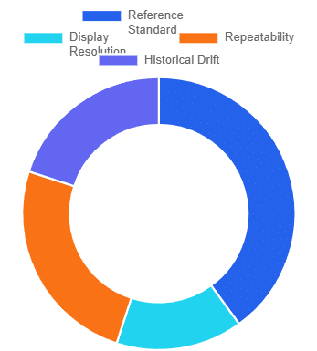
Calculating the Combined and Expanded Uncertainty
Combined standard uncertainty is calculated by taking the square root of the sum of the squares of all individual components. We then multiply this result by a coverage factor of k equals 2 to determine the expanded uncertainty. To compile the budget, convert all individual uncertainty components into standard uncertainties. This step often requires dividing rectangular distributions by the square root of three. Once normalized, combine the independent components using the law of propagation of uncertainty.The Importance of Test Uncertainty Ratio (TUR)
The Test Uncertainty Ratio compares the tolerance of the instrument under test to the expanded uncertainty of the calibration system. Maintaining a high ratio ensures that the calibration process can reliably detect out-of-tolerance conditions. A standard metrological rule of thumb is to maintain a Test Uncertainty Ratio of four to one or greater. This means that your reference system must be at least four times more accurate than the instrument you are testing. If the ratio drops too low, you risk making false acceptance decisions. When calibrating modern high-precision digital indicators, achieving a four-to-one ratio can be challenging. In these demanding scenarios, you must use extremely accurate reference equipment, such as deadweight testers. Alternatively, you must apply sophisticated guard-banding techniques to manage the increased decision risk.Prominent Pressure Indicator Models Calibration Reference Table
This reference table outlines industry-standard high-precision pressure instruments, highlighting their typical industrial applications and the recognized international guidelines used for their calibration.| Manufacturer | Model | Primary Industrial Application | Applicable Calibration Standard |
|---|---|---|---|
| Fluke Calibration | 700G Series | Field verification and onsite pressure calibration | EURAMET cg-17 / ASME B40.7 |
| Druck (Baker Hughes) | DPI 104 | Precision laboratory reference and process monitoring | EURAMET cg-17 / BS EN 837 |
| Additel | 681 Series | Industrial test bench reference and pressure transmitter testing | EURAMET cg-17 / ASME B40.7 |
| Beamex | MC6 | Multifunction field calibrator and high-accuracy reference standard | ISO/IEC 17025 / EURAMET cg-17 |
| Rosemount | 3051S Reference | High-end process control verification and custody transfer | ISO/IEC 17025 / EURAMET cg-17 |
Navigating Audits: ISO 17025 and Traceability Requirements
Navigating audits successfully requires demonstrating an unbroken chain of metrological traceability back to national standards. Furthermore, your laboratory must maintain complete documentation that details how every measurement is linked to international SI units.Unbroken Chains of Metrological Traceability to SI Units (NIST/PTB)
An unbroken chain of traceability ensures that every measurement is linked back to primary standards maintained by national institutes like NIST or PTB. Consequently, this chain guarantees that a pressure measurement made in your facility is globally recognized.Executing a proper ISO 17025 pressure calibration requires absolute adherence to this traceability hierarchy. Traceability begins with the primary standards maintained by national metrology institutes. These institutes calibrate the working standards used by accredited primary laboratories. Subsequently, those primary laboratories calibrate your secondary standards, which you then use to calibrate your field instruments.
To prove traceability during an audit, you must present valid, unexpired certificates for all reference standards used in the calibration. Each certificate must display the accreditation body logo and a unique certificate number. This documentation provides a clear paper trail that satisfies both internal quality managers and external inspectors.Understanding Statement of Conformity and Decision Rules
A statement of conformity declares whether an instrument meets its specified performance tolerances after calibration. To make this declaration legally and technically sound, the laboratory must apply a defined decision rule that accounts for measurement uncertainty. When a measured value lies close to the tolerance limit, the measurement uncertainty makes it impossible to be 100 percent certain of compliance. Therefore, you must use a formal decision rule, such as simple acceptance or guard-banding, to determine compliance. This rule defines how the expanded uncertainty is factored into the pass or fail decision. Under ISO/IEC 17025 guidelines, the chosen decision rule must be communicated to and agreed upon with the customer beforehand. Applying these rules prevents laboratories from issuing false pass certificates for borderline instruments. Consequently, it protects your operation from installing a faulty device back into critical production lines.What Must Appear on an ISO 17025 Accredited Calibration Certificate
An accredited calibration certificate must contain specific details, including the laboratory accreditation scope, the unique identification of the device, and the calculated measurement uncertainty. Failing to include these key elements invalides the compliance status of the document. The certificate must clearly state the environmental conditions, such as temperature and humidity, recorded during the test. Furthermore, it must explicitly list the physical reference standards used, proving their active traceability. The measurement data must present both the reference values and the corresponding instrument readings. Importantly, the certificate must show the expanded uncertainty associated with every single measurement point. You must also include a clear statement regarding the traceability chain and any decision rules applied during conformity assessment. These detailed components transform a simple test sheet into a legally binding quality document.Common Out-of-Tolerance (OOT) Risks and How to Prevent Them
Out-of-tolerance instruments present significant operational risks, including contaminated product batches, compromised safety systems, and failed regulatory audits. Preventing these risks requires establishing proactive verification schedules and robust response protocols.How to Set Practical Calibration Intervals for Master Standards
Setting practical calibration intervals involves analyzing historical drift patterns and the severity of the instrument’s operating environment. Instead of relying on static annual cycles, you should adjust intervals dynamically based on actual stability data. Begin by reviewing the historical calibration data of your instruments over at least three consecutive cycles. If the device consistently demonstrates minimal drift, you can safely extend the interval using methods described in OILM D10. Conversely, if the device exhibits significant drift, you must shorten the interval immediately. Additionally, consider the physical environment where the instrument operates. Devices subjected to harsh field conditions or high vibration require more frequent verification than those kept in clean laboratories. Implementing an onsite pressure calibration program helps verify field units quickly without removing them from service.Root Cause Analysis (RCA) Protocol for Out-of-Tolerance Instruments
The Root Cause Analysis protocol is a mandatory quality process triggered immediately when an instrument is found out-of-tolerance. This investigation determines when the failure occurred and assesses its impact on all products manufactured since the last calibration. First, quarantine the out-of-tolerance instrument immediately to prevent further use. Next, retrieve all production records linked to that specific device since its last successful calibration. You must evaluate whether the measurement error could have resulted in the release of non-conforming products. Simultaneously, investigate the physical cause of the failure. Check for signs of overpressure, chemical contamination, or mechanical impact on the sensor. Finally, document your findings, implement corrective actions, and increase the calibration frequency for that instrument to prevent future failures.Frequently Asked Questions (FAQ)
What is the recommended calibration interval for a digital pressure calibrator?
The standard recommended interval for a digital pressure calibrator is twelve months. However, you should adjust this frequency based on the stability of the instrument and its operating environment. Highly critical reference standards used in aerospace or pharmaceutical laboratories often require a six-month cycle. Conversely, rugged field calibrators may be verified more frequently using intermediate cross-checks against a stable reference.Why is onsite pressure calibration necessary for industrial facilities?
Implementing an onsite pressure calibration program minimizes production downtime by eliminating the need to ship critical instruments to external laboratories. Furthermore, calibrating instruments in their actual operating environment accounts for site-specific factors such as local gravitational differences, piping stresses, and ambient temperature profiles. This real-world verification provides a more accurate assessment of how the instrument performs during actual production runs.How does ISO 17025 pressure calibration differ from standard calibration?
An accredited ISO 17025 pressure calibration requires a laboratory to operate under a strictly audited quality management system. This process demands a fully documented uncertainty budget, proven metrological traceability, and regular participation in proficiency testing. In contrast, a standard commercial calibration may only provide a basic comparison of readings without calculating measurement uncertainty or verifying the traceability chain.What is the difference between digital pressure indicator calibration and digital pressure calibrator calibration?
A digital pressure indicator only displays pressure values, whereas a digital pressure calibrator is designed to both measure and generate or control precise pressure levels. Consequently, digital pressure calibrator calibration is a more complex process. It requires calibrating both the internal electronic measurement sensors and the physical pressure generation mechanisms, such as hand pumps or automated controllers, to ensure complete system accuracy.What should I do if a digital pressure indicator fails its As-Found calibration?
If an instrument fails its As-Found verification, you must initiate an Out-of-Tolerance investigation immediately. First, isolate and quarantine the instrument to ensure it is not returned to service. Second, assess the potential impact of the measurement deviation on all products processed with that device since its last successful calibration. Finally, perform a technical adjustment, conduct a complete As-Left calibration, and document the entire corrective action process.Choosing an Accredited Pressure Calibration Partner
Choosing the right calibration partner requires verifying that their laboratory accreditation scope covers your specific pressure ranges and uncertainty requirements. Partnering with an expert team guarantees that your critical instruments are calibrated to the highest global standards. Our accredited calibration laboratory provides comprehensive pressure measurement services designed to keep your facility compliant and efficient. We maintain extremely low Calibration and Measurement Capabilities, allowing us to verify high-accuracy reference standards with absolute precision. Our state-of-the-art facilities and experienced metrologists ensure that your instruments are returned to you quickly, minimizing operational downtime.Whether you require advanced laboratory verification or rapid onsite pressure calibration services, our comprehensive ISO 17025 pressure calibration solutions deliver detailed, audit-ready documentation that meets all ISO/IEC 17025 guidelines. Partner with us today to secure your digital pressure indicator calibration quality, mitigate compliance risks, and guarantee the stability of your industrial processes.
Frequently asked questions
What is Digital Pressure Indicator Calibration?
How often should a Digital Pressure Indicator be calibrated?
What standards apply to Digital Pressure Indicator Calibration?
What is included on the certificate?
Can you calibrate the Digital Pressure Indicator on-site?
Need Digital Pressure Indicator calibration?
ANAB-accredited, NIST-traceable, fast turnaround — in-lab or on-site across the USA.
Contact us for a quoteReferences & industry standards
- ISO/IEC 17025 testing & calibration laboratory requirements
- NIST calibration services and measurement traceability
- NIST Pressure and Vacuum Group
- A2LA / ANAB accreditation for calibration laboratories
External standards bodies. Techmaster Electronics is an ISO/IEC 17025-accredited, NIST-traceable calibration laboratory.
Related reading: deadweight tester vs. digital pressure calibrator – which pressure standard does your lab need

Khanh Nguyen is the Marketing Manager at Techmaster Electronics, a B2B marketing leader covering the test, measurement, and ISO/IEC 17025 accredited calibration industry across the US and Vietnam markets.