
MA Process Clamp Meter Calibration
Accuracy across the range
How mA Process Clamp Meter calibration works
- Intake & visual inspection
- Environmental stabilization
- As-found measurement
- Comparison to NIST-traceable standards
- Adjustment if required
- As-left results & certificate
Your calibration, covered
In-lab vs on-site calibration
In-lab calibration
- Accredited bench with full reference standards
- Best achievable measurement uncertainties
- Pickup & return logistics handled
- Ideal for precision and reference work
On-site calibration
- We calibrate the mA Process Clamp Meter at your facility
- No shipping risk or transit downtime
- As-found data captured before any move
- Ideal for fixed, large or sensitive assets
In-depth guide
1. Introduction
In the field of industrial automation, mA Process Clamp Meter calibration is a fundamental requirement to ensure that control loops operate without error. Even a microscopic deviation in a 4-20mA control loop can lead to catastrophic system failures, incorrect sensor readings, or costly production downtime. Standard electrical clamp meters often lack the specialized sensitivity required to detect these subtle shifts, creating a dangerous “blind spot” where technicians might misdiagnose healthy components or ignore failing PLC inputs due to instrument drift. Professional calibration, following an ISO/IEC 17025-aligned methodology, is the essential solution to ensure your instrument operates within its intended parameters, establishing rigorous traceability and reducing measurement risk in high-stakes industrial environments.
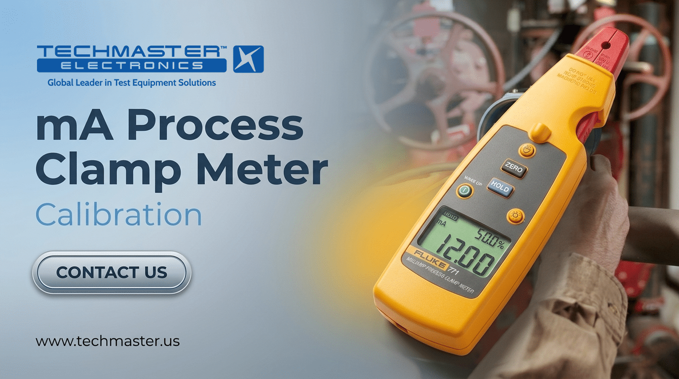
2. Overview: The Role of mA Process Clamp Meters
An mA Process Clamp Meter is a high-precision instrument designed to measure low-level DC current in 4-20mA control loops without breaking the circuit. It is a critical tool for troubleshooting transmitters, PLCs, and valves while the process remains live and operational. Unlike standard clamps that rely on simple induction for high AC current, these specialized meters utilize advanced Hall Effect or Fluxgate technology. These sensors are capable of detecting minute magnetic fields generated by milliamp-level currents. In a typical industrial loop, they allow a technician to verify signal integrity across the entire path—from the sensor output to the controller input—without causing signal interruptions that could trigger emergency shutdowns.3. mA Process Clamp Meter Calibration under ISO/IEC 17025
Calibrating an mA Process Clamp Meter is a rigorous scientific process. Because these instruments detect minute magnetic fields to measure low-level DC current in 4-20mA control loops, even microscopic environmental or mechanical variables can introduce critical errors. The following sequence ensures rigorous traceability and peak reliability.
Stabilize in a climate-controlled environment to prevent thermal drift of sensitive magnetic sensors.
Verify physical integrity and jaw cleanliness. Microscopic debris causes significant measurement errors.
Perform a “Manual Zero” in the final test orientation to cancel out the Earth’s magnetic field.
Use a precision standard and multi-turn current coil to amplify the magnetic field for stable comparison.
Measure ascending/descending intervals (25-100%) to identify magnetic memory in the sensor core.
Step-by-Step Procedure for mA Process Clamp Meter Calibration
- Environmental Conditioning: Stabilize the instrument in a climate-controlled environment for several hours before testing. This step is vital because the sensitive magnetic sensors in mA clamps react quickly to thermal drift.
- Mechanical & Visual Inspection: Technicians inspect the device for physical integrity, battery health, and the cleanliness of the jaw faces. The magnetic circuit must close perfectly to measure low mA levels; therefore, even microscopic debris on the jaw mating surfaces causes significant measurement errors.
- The Zeroing Protocol: Before applying test signals, perform a “Manual Zero” while holding the meter in the exact orientation of the final test. This action cancels out the local influence of the Earth’s magnetic field and any residual magnetism in the jaw core.
- Reference Signal Application: Use a precision current standard to generate specific signals. Typically, technicians pass these signals through a multi-turn current coil to amplify the magnetic field, providing a more stable and accurate comparison for the clamp’s sensor.
- Linearity and Hysteresis Verification in mA Process Clamp Meter Calibration: Take measurements at various intervals (e.g., 25%, 50%, 75%, and 100% of the range). Technicians must record data in both ascending and descending order to identify any “magnetic memory” or hysteresis within the sensor core.
Traceability and Measurement Uncertainty
To comply with ISO/IEC 17025, every calibration result must be linked to the International System of Units (SI). This is achieved through an unbroken chain of comparisons back to national metrology institutes. Furthermore, a professional calibration report accounts for Measurement Uncertainty. This is not a simple “error” calculation but a statistical analysis that includes:- The stability and history of the reference standard.
- The resolution and repeatability of the device under test (DUT).
- The impact of environmental variables like temperature and ambient electromagnetic interference (EMI).
4. The Critical Impact of Calibration on Operational Risk
Ignoring the calibration schedule for mA process clamp meters introduces significant latent risks into industrial infrastructure. Beyond simple measurement error, an uncalibrated meter can compromise the entire “Trust Chain” of a plant’s automation system. In high-precision environments such as pharmaceutical manufacturing or chemical processing, a drift of just 0.05mA can be the difference between a successful batch and a complete product rejection due to incorrect temperature or pressure feedback. From a compliance perspective, failing to maintain an ISO/IEC 17025-compliant calibration log can lead to severe audit non-conformities, potentially revoking a facility’s operational license or safety certifications. Furthermore, uncalibrated instruments often lead to “false positives” during troubleshooting—where a healthy valve or transmitter is replaced unnecessarily—costing thousands of dollars in wasted components and technician hours. By adhering to professional calibration standards, organizations not only ensure technical accuracy but also fortify their legal and economic standing against the uncertainties of industrial measurement.5. Expert Advice for Equipment Reliability
Expert Tip 1: The Importance of “Zeroing” in the Field Always zero your meter immediately before clamping onto a wire. Because these devices are so sensitive, simply rotating the meter in your hand can change the reading by a fraction of a milliamp due to changes in its alignment with the Earth’s magnetic poles. Expert Tip 2: Protecting the Magnetic Circuit The jaw mating surfaces are the most critical part of the tool. Avoid snapping the jaws shut, as this can cause micro-fractures in the ferrite core. Periodically clean the mating surfaces with a lint-free cloth to ensure a perfect metal-to-metal seal. Expert Tip 3: Strategic Storage Never store your mA clamp meter near large motors, speakers, or magnets. Strong external magnetic fields can “permeate” the sensor core, leading to an offset that is impossible to zero out without professional degaussing.6. FAQ: User Questions – Expert Answers
Q: How often should I calibrate my process clamp meter? While the industry accepts a 12-month interval as standard, we recommend a 6-month cycle for meters operating in extreme temperatures or high-criticality loops. In these scenarios, instrument failure could lead to significant financial or safety consequences.
Q: Why does my meter show a reading when it isn’t clamped to anything? High-sensitivity DC sensors naturally exhibit this characteristic. Residual magnetism in the jaws or the ambient magnetic field causes these ghost readings. You must use the “Zero” function before each measurement to eliminate this offset. Q: Can I use a standard multimeter clamp for 4-20mA troubleshooting? No. Manufacturers design standard clamps for amperes, not milliamps. They lack the necessary resolution and specialized magnetic shielding required to accurately measure the tiny signals in process control. Q: Does the position of the wire inside the jaws affect accuracy? Yes. For the highest accuracy, you should center the wire within the jaws. Most professional clamps include alignment marks; placing the wire off-center introduces “positioning errors” due to non-uniform magnetic flux distribution. Q: What is the main difference when calibrating sourcing models (like Fluke 773)? A basic model only requires verification of its measurement function. In contrast, sourcing models demand a two-part calibration: our technicians must verify both the clamp’s measurement accuracy and the precision of the internal signal generator used to source or simulate mA signals.7. Conclusion & CTA
In the world of process control, precision is not optional—it is the foundation of safety and efficiency. An mA Process Clamp Meter is a sophisticated diagnostic tool that requires regular, professional attention to maintain its integrity.Adhering to these 5 distinct steps guarantees that your mA Process Clamp Meter provides the rigorous traceability required for safe, efficient industrial automation.
Frequently asked questions
What is mA Process Clamp Meter Calibration?
How often should a mA Process Clamp Meter be calibrated?
What standards apply to mA Process Clamp Meter Calibration?
What is included on the certificate?
Can you calibrate the mA Process Clamp Meter on-site?
Need mA Process Clamp Meter calibration?
ANAB-accredited, NIST-traceable, fast turnaround — in-lab or on-site across the USA.
Contact us for a quoteReferences & industry standards
- ISO/IEC 17025 testing & calibration laboratory requirements
- NIST calibration services and measurement traceability
- A2LA / ANAB accreditation for calibration laboratories
External standards bodies. Techmaster Electronics is an ISO/IEC 17025-accredited, NIST-traceable calibration laboratory.
