

How to Use an Earth Ground Resistance Tester: Setup, Operation & Best Practices
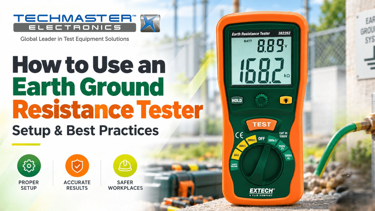
Knowing how to use an earth ground resistance tester helps electrical teams check grounding systems and protect people and equipment. These testers measure the resistance between an earth electrode and the surrounding soil. As a result, engineers can assess grounding performance and find possible issues.
However, accurate results depend on more than the tester itself. Proper stake placement, good lead connections, suitable test settings, and correct test methods all matter. Therefore, users should follow the instrument manual and the site’s electrical safety procedures before starting a test.
1. Technical Principles: Fall-of-Potential Testing and Resistance
1.1. How Does Earth Ground Resistance Testing Work?
Earth ground resistance testers measure how strongly the ground resists electrical current. One common method is the Fall-of-Potential method.
First, the tester sends a test current through the earth between the electrode under test and an auxiliary current stake (C). Next, a potential stake (P) measures the voltage difference in the soil. The tester then uses these readings to calculate resistance.
A simplified test setup looks like this:
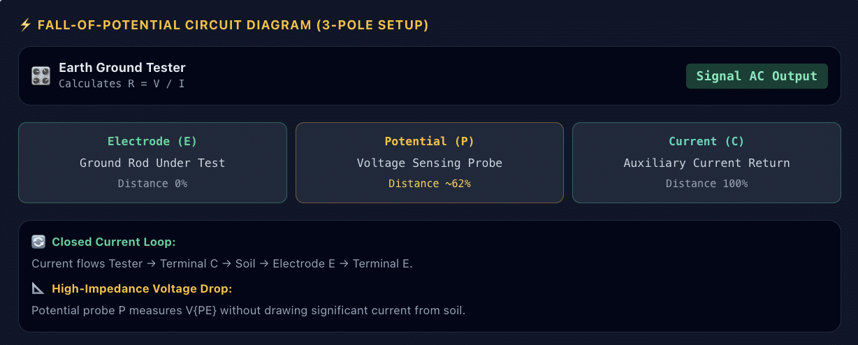
The tester calculates resistance using Ohm’s Law:
Resistance (R) = Voltage (V) / Current (I)
Therefore, if the tester measures voltage in volts and current in amperes, it reports resistance in ohms (Ω).
1.2. Why Does Test Frequency Matter?
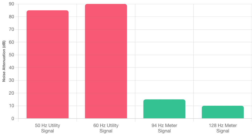
Many earth ground testers use an AC test signal instead of simple DC. This approach can help reduce the effects of stray electrical noise and electrode polarization.
For example, power systems often carry 50 Hz or 60 Hz signals. Therefore, some testers use another test frequency to help separate the measurement signal from power-line interference.
However, not every tester uses the same frequency. Always check the manufacturer’s specifications and select the test mode that suits the site conditions.
2. Industrial Applications: Where Ground Testing Matters
Earth ground resistance testing supports electrical safety in many settings. For example, maintenance teams use these tests to check grounding systems and investigate unusual readings.
- Power substations and transmission systems: Teams assess grounding systems that help manage fault currents and lightning effects. In addition, they may use relevant IEEE guidance when planning and reviewing tests.
- Telecommunications towers and data centers: Ground testing helps teams assess grounding and lightning protection systems. As a result, they can better protect sensitive equipment.
- Solar and wind farms: Engineers test grounding systems across renewable energy sites. Therefore, they can identify issues that may affect electrical safety.
- Industrial plants and chemical facilities: Maintenance teams check grounding paths and bonding connections. In addition, proper grounding helps control electrical hazards in the workplace.
However, the correct test method and acceptance limit depend on the installation, local codes, system design, and project requirements.
3. How to Set Up and Use an Earth Ground Resistance Tester
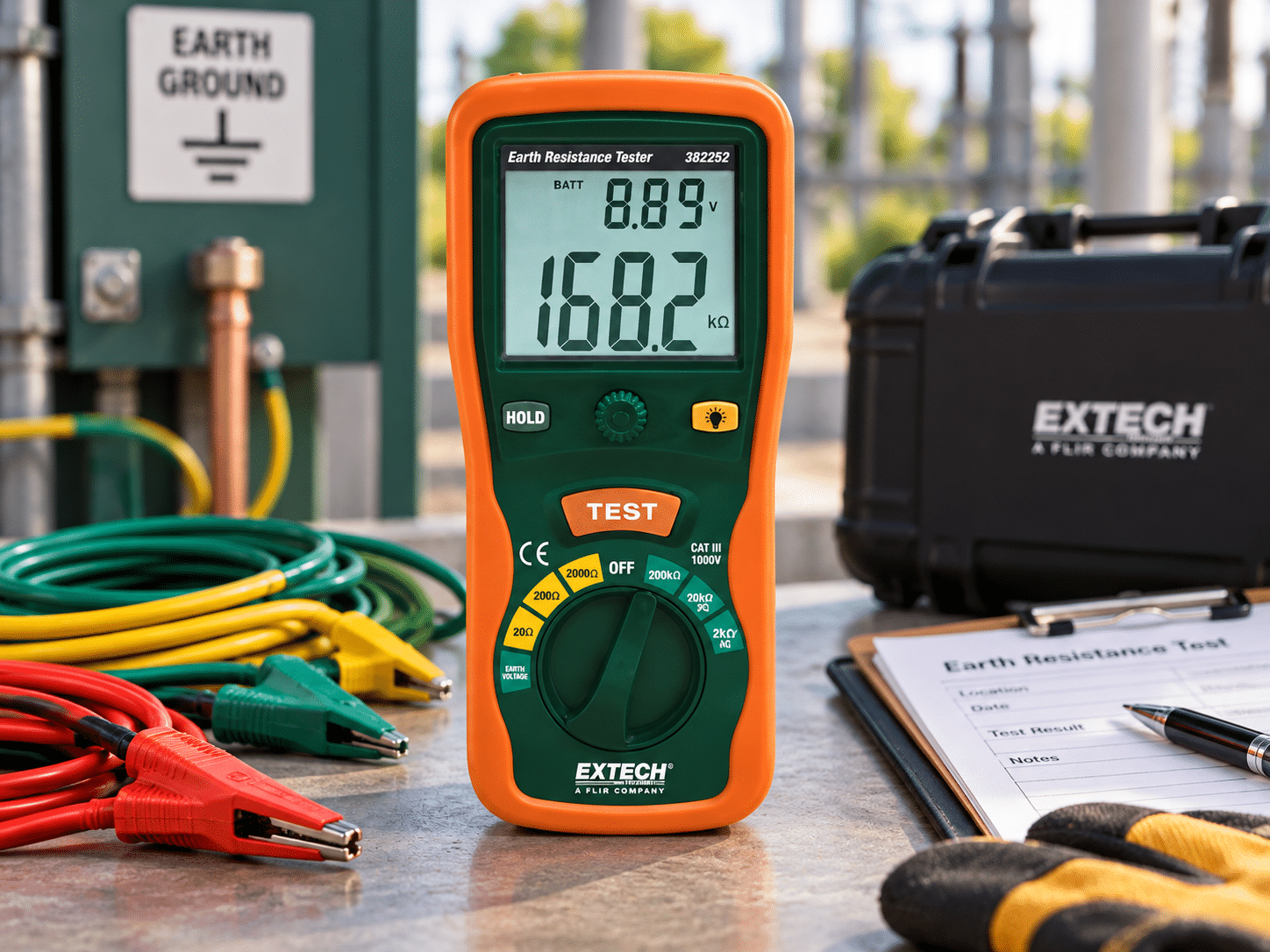
Before starting, read the tester manual and review the site’s safety procedure. Do not disconnect a main grounding conductor or alter a grounding system unless an authorized, qualified person has confirmed that the work is safe.Grounding conductors may carry dangerous current even when equipment appears to be off.
Also, do not assume that switching equipment off makes a grounding system safe to handle. Follow the site’s isolation, verification, and electrical safety requirements.
Step 1: Inspect the Tester and Leads
First, check the tester casing, battery, connectors, clamps, and test lead insulation.
Look for cracks, exposed wires, corrosion, or loose connections. In addition, confirm that the leads and accessories match the tester’s ratings.
Next, perform any built-in checks that the manufacturer recommends. However, do not assume that a continuity check or lead-zero function verifies the full accuracy of the instrument.
Step 2: Place the Auxiliary Stakes
Next, prepare the test area and check for buried utilities before driving any stakes into the soil.
For a Fall-of-Potential test, place the current stake (C) and potential stake (P) in a straight line from the electrode under test (E). Then, space the stakes according to the instrument manual and the test method.
The required distance depends on the grounding system and site layout. Therefore, do not use one fixed distance for every installation.
Also, check that the stakes make suitable contact with the soil. Dry or rocky ground may affect the reading, so follow the manufacturer’s guidance if the tester reports poor stake contact.
Step 3: Connect the Test Leads
After placing the stakes, connect the leads to the correct terminals.
For a common three-wire test, the connections typically link the tester to the electrode under test, the potential stake, and the current stake. However, lead colors and terminal labels can vary by model.
Therefore, follow the markings on your instrument rather than relying on wire color alone.
Next, check each connection for firm contact. Dirty clamps, loose leads, or corroded terminals can cause unstable readings.
Step 4: Select the Test Mode
Now, turn on the tester and choose the correct measurement mode.
For example, a three-wire Fall-of-Potential test may use a 3-pole earth resistance setting. Other instruments may offer selective or stakeless methods.
Then, select the test frequency if your model allows it. If the display shows a noise warning, follow the manual’s guidance before continuing.
In addition, confirm that the selected mode matches the grounding system and the test objective.
Step 5: Run the Test and Record the Result
Once the setup is ready, start the measurement and wait for the tester to complete its cycle.
Next, check the stability indicator and review any warning messages. If the reading changes sharply or the instrument reports excessive noise, investigate the setup before accepting the result.
Finally, record the resistance value, test method, location, date, and relevant site conditions. This information helps teams compare future readings and track changes over time.
Step 6: Review and Confirm the Results
After recording the result, compare it with the applicable design limits, local requirements, and project specifications.
For example, some projects set a target resistance value for a particular grounding system. However, no single value suits every installation.
Therefore, do not treat 5 Ω or 25 Ω as universal acceptance limits. Instead, use the limit that applies to the system under test.
If the result falls outside that limit, have a qualified person review the test setup and investigate the grounding system before deciding on corrective work.
Frequently Asked Questions
1. How do you use an earth ground resistance tester?
Using an earth ground resistance tester involves disconnecting the main grounding electrode, driving auxiliary current and potential stakes into the soil in a straight line, connecting 3-wire test leads, and executing a Fall-of-Potential test to measure earth resistance in ohms.
2. What is the ideal earth ground resistance value for electrical systems?
An earth ground resistance value of 25Ω or less is generally acceptable for standard commercial installations under the National Electrical Code (NEC). However, sensitive data centers, substations, and telecommunication sites frequently require5 Ω or less.
3. Why must the main grounding conductor be disconnected during testing?
Disconnecting the main grounding conductor ensures that parallel grounding paths from utility neutrals or bonded building steel do not artificially lower the resistance reading, allowing the meter to test only the isolated earth electrode system.
4. What causes erratic or unstable readings on an earth ground tester?
Erratic readings are typically caused by dry, high-resistivity soil around auxiliary stakes, poor test lead contact, high stray electrical noise from nearby power lines, or electrochemical polarization around the metal stakes.
5. How often should an earth ground resistance tester be calibrated?
An earth ground resistance tester should undergo ISO/IEC 17025 accredited calibration every 12 months to maintain measurement accuracy, verify test frequency stability, and satisfy regulatory quality audits.
How to Use an Earth Ground Resistance Tester
Accurate earth ground resistance measurements protect personnel, safeguard critical infrastructure, and verify fault-current dissipation paths. Master Fall-of-Potential setup, auxiliary stake geometry, AC noise filtering, and step-by-step field operations.

Calibration engineer at Techmaster Electronics, ISO/IEC 17025 accredited laboratory with 35+ years of metrology expertise.