
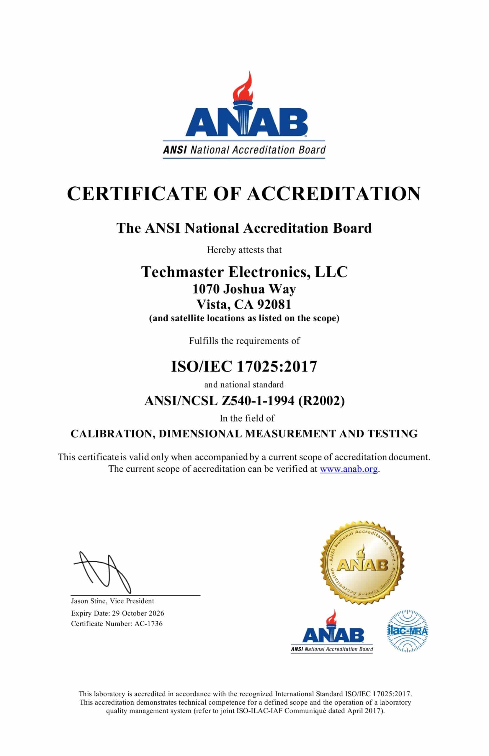
How to Use a Reference Voltage Standard: Setup, Operation & Best Practices
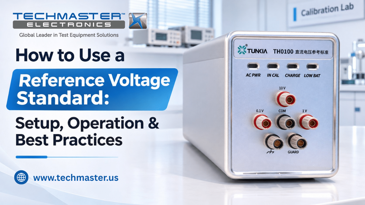
In precision testing and calibration, a stable DC voltage reference helps teams maintain accurate electrical measurements. However, even a small change in temperature, cable connection, or instrument condition can affect the reading. Therefore, users need to understand how to use a reference voltage standard and follow a clear operating process. A careful setup helps reduce measurement errors and supports reliable test results. In addition, good records make it easier to track voltage changes over time. By following the steps below, technicians can protect measurement quality and support traceability throughout the calibration process.
1. Technical Principles of Reference Voltage Standards
1.1. How a Reference Voltage Standard Works
A reference voltage standard provides a known DC voltage for checking and calibrating other instruments. For example, many solid-state standards use a temperature-compensated Zener diode or another stable electronic circuit to produce a steady output. Some models also include an internal temperature control system. This system helps limit the effect of room temperature changes on the voltage output. However, not every model uses the same design, output range, or control method. Therefore, always check the manufacturer’s manual before use. Common output levels include 10 V, 1 V, and other values, depending on the model.
During a measurement, several factors can affect the output voltage. For instance, temperature changes, component aging, and unwanted voltage at cable connections may cause small differences.
A simplified model is:
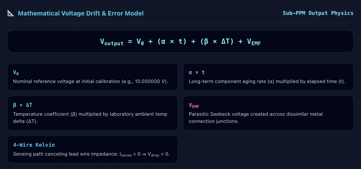
This model helps explain possible sources of voltage change. However, actual performance depends on the design and specifications of the instrument.
1.2. Common Causes of Voltage Errors
Several factors can affect a reference voltage standard during daily use. Therefore, technicians should check the following conditions before taking measurements.
- Thermal EMF: When two different metals meet at different temperatures, they can create a small unwanted voltage. As a result, the meter may show a reading that differs from the actual reference value.
- Temperature changes: Room temperature changes can affect the output of some reference standards. In addition, a faulty temperature control system may reduce output stability.
- Component aging: Electronic components can change over time. Consequently, the output voltage may slowly move away from its earlier value.
- Poor connections: Dust, moisture, and loose terminals can affect electrical contact. Therefore, technicians should inspect connectors before each measurement.
- Electrical noise: Nearby equipment and poor cable layout may introduce unwanted signals. For this reason, keep the measurement setup away from avoidable sources of interference.
2. Industrial Applications of Reference Voltage Standards
Reference voltage standards support accurate measurements in many industries. In particular, they help calibration teams check instruments that measure or generate DC voltage.
- Calibration laboratories: Technicians use voltage references to check digital multimeters, precision calibrators, and other electrical instruments. As a result, they can maintain consistent measurement results.
- Semiconductor testing: Manufacturers use stable voltage references when testing analog-to-digital converters (ADCs), digital-to-analog converters (DACs), and other electronic parts. Therefore, they can check whether these devices meet their performance limits.
- Aerospace and defense: Test teams use voltage references to check electronic systems and support maintenance work. In addition, reliable voltage measurements help maintain equipment quality.
- Medical device manufacturing: Manufacturers use precise voltage sources to test sensor circuits and electronic control systems. Consequently, they can support consistent product performance.
3. How to Set Up and Use a Reference Voltage Standard
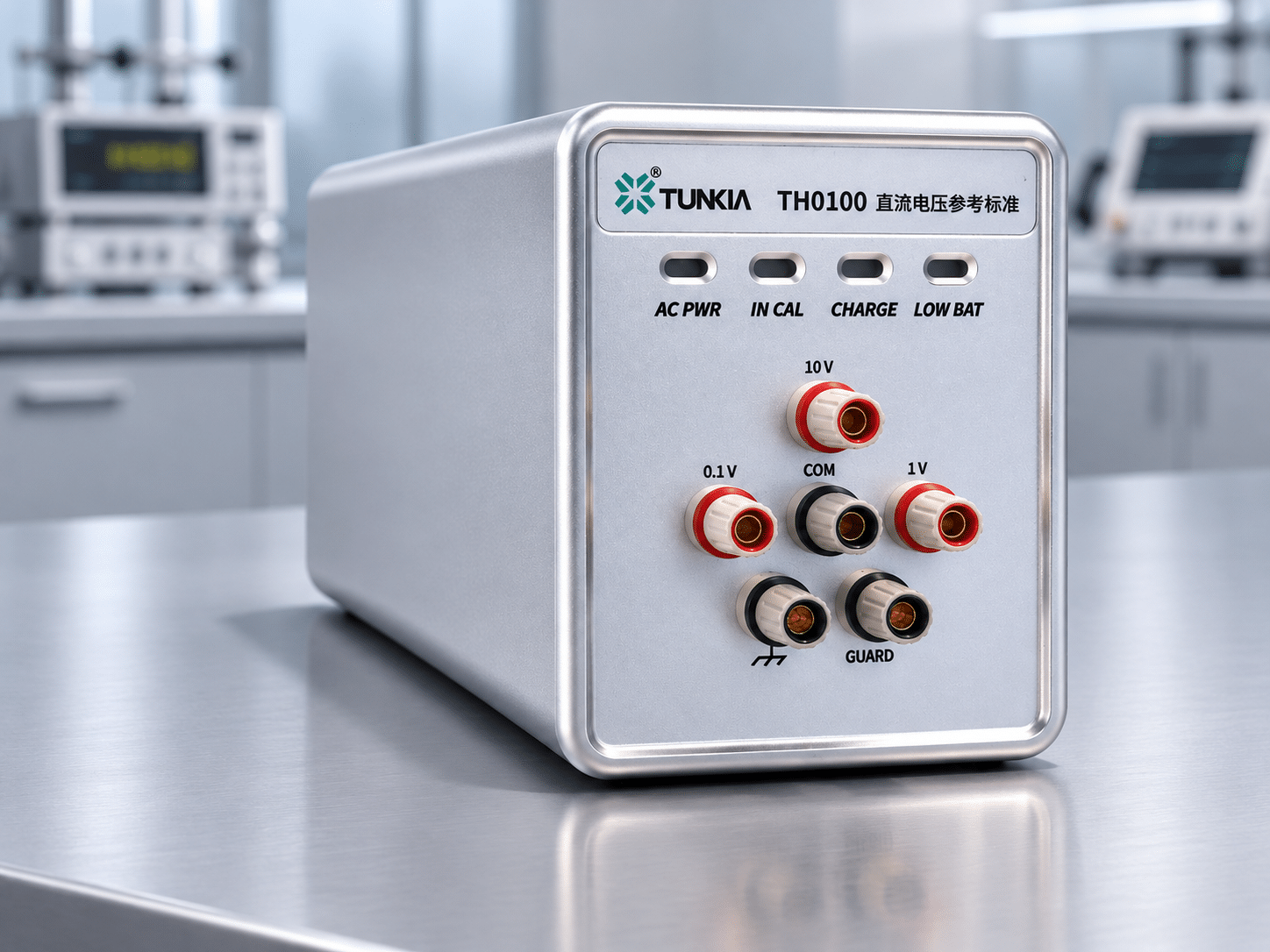
A suitable setup helps reduce errors and improve measurement consistency. Before starting, read the instrument manual and confirm that the selected output meets the needs of your test.
1. Prepare the Work Area and Cables
First, place the reference voltage standard on a stable work surface. Next, check the room conditions and remove avoidable sources of electrical noise.
Follow these steps:
- Keep the work area clean and dry. Also, avoid placing the instrument near heat sources or equipment that may cause strong electrical interference.
- Inspect the output terminals and cable connectors. If you find dust or signs of damage, follow the manufacturer’s cleaning instructions.
- Use suitable low-thermal cables when the measurement requires high accuracy. These cables help reduce unwanted voltage at metal connections.
- Keep cable connections short and secure. In addition, avoid unnecessary contact between different metal types.
- Check room temperature and humidity. Finally, record these conditions when your laboratory procedure requires them.
2. Power On and Prepare the Instrument
Before taking measurements, check the power requirements and warm-up guidance in the user manual.
- Connect the instrument to a suitable power source. If the manufacturer recommends continuous operation, follow that guidance.
- Allow the instrument to reach its specified operating condition. However, warm-up time varies by model, so do not apply one fixed period to every reference standard.
- Check the status indicators and display. If the instrument shows an error or warning, resolve it before continuing.
- Confirm the selected output voltage. For example, choose 10 V or 1 V only when that value matches your measurement procedure.
- Record the instrument’s operating condition when your quality system requires it.
3. Connect the Reference Standard to a Multimeter
Next, connect the reference standard to a suitable digital multimeter. The meter must have enough resolution and accuracy for the measurement task.
- Check the input limits of the multimeter before connecting the leads.
- Connect the positive and negative leads to the correct output terminals.
- Use the Guard terminal only when the instrument design and measurement method support it. In addition, follow the connection diagram in the manuals.
- Keep the cables away from heat sources and strong air currents. This helps reduce temperature differences at the connections.
- Check each connection before enabling the output.
4. Measure and Record the Output Voltage
After completing the connections, allow the reading to settle according to the instrument manual and your test procedure.
Then, follow these steps:
- Select the required voltage output.
- Read the multimeter display and wait for a stable result.
- Record the voltage, range, date, time, and room conditions.
- Repeat the measurement when your procedure requires multiple readings.
- Compare the result with the reference value and the allowed tolerance.
You can calculate the relative voltage error with this formula:
Voltage error (%) = [(Vmeasured − Vref) / Vref] × 100
Where:
- Vmeasured is the voltage shown by the measuring instrument.
- Vref is the reference voltage value used for comparison.
For example, if the measured value differs from the reference value, calculate the error and compare it with the acceptance limit in your procedure. However, do not judge instrument performance using the error value alone. You should also consider measurement uncertainty and the specifications of both instruments.
5. Review Results and Maintain Measurement Records
Finally, review the results before using the reference standard for other calibration tasks.
- Check whether the readings fall within the expected limits.
- Compare recent results with earlier records to identify changes over time.
- Investigate unusual readings before continuing with the calibration work.
- Keep calibration certificates, measurement records, and maintenance notes in an organized file.
- Follow the manufacturer’s instructions for storage, handling, and routine checks.
As a result, your team can track instrument performance and make better decisions about future calibration needs.
Frequently Asked Questions
1. How do you use a reference voltage standard correctly to avoid thermal EMF errors?
To avoid thermal EMF errors when using a reference voltage standard, use solid tellurium-copper or gold-plated spade connectors, shield interconnections from ambient air currents, and perform positive/negative lead-reversal measurement cycles to cancel thermal junction voltages mathematically.
2. Why must a reference voltage standard remain powered on continuously?
A reference voltage standard must remain powered on continuously to maintain internal oven thermal equilibrium and prevent semiconductor lattice relaxation in the buried Zener diode. Interrupting power resets thermal stabilization, requiring up to 72 hours of warm-up time to re-establish sub-ppm stability.
3. How often should a reference voltage standard undergo accredited calibration?
A reference voltage standard should undergo ISO/IEC 17025 accredited calibration every 12 months. Newly acquired standards or units demonstrating non-linear drift characteristics should be calibrated on a 6-month cycle until their annual drift rate is established.
4. What is the difference between a working voltage reference and a primary voltage standard?
A working voltage reference is a robust solid-state unit used daily to calibrate multimeters and field equipment. A primary voltage standard (such as a Josephson Junction array or master zener reference) resides in an accredited metrology lab to calibrate working standards.
5. What causes long-term voltage drift in solid-state reference standards?
Long-term voltage drift is driven by mechanical aging of internal buried Zener diodes, micro-stress changes in precision wire-wound resistor dividers, and minor component aging inside the internal temperature-regulated oven control loop.
How to Use a Reference Voltage Standard: Setup, Operation & Calibration
Master the operational execution, mathematical drift modeling, thermal EMF elimination, 4-wire active guarding, and ISO/IEC 17025 accredited calibration procedures necessary to maintain sub-PPM DC measurement integrity across lab and field environments.

Calibration engineer at Techmaster Electronics, ISO/IEC 17025 accredited laboratory with 35+ years of metrology expertise.