

Teraohmmeter Calibration
Accuracy across the range
How Teraohmmeter calibration works
- Intake & visual inspection
- Environmental stabilization
- As-found measurement
- Comparison to NIST-traceable standards
- Adjustment if required
- As-left results & certificate
Your calibration, covered
In-lab vs on-site calibration
In-lab calibration
- Accredited bench with full reference standards
- Best achievable measurement uncertainties
- Pickup & return logistics handled
- Ideal for precision and reference work
On-site calibration
- We calibrate the Teraohmmeter at your facility
- No shipping risk or transit downtime
- As-found data captured before any move
- Ideal for fixed, large or sensitive assets
In-depth guide
Teraohmmeter Calibration: Securing Precision in Ultra-High Resistance Metrology
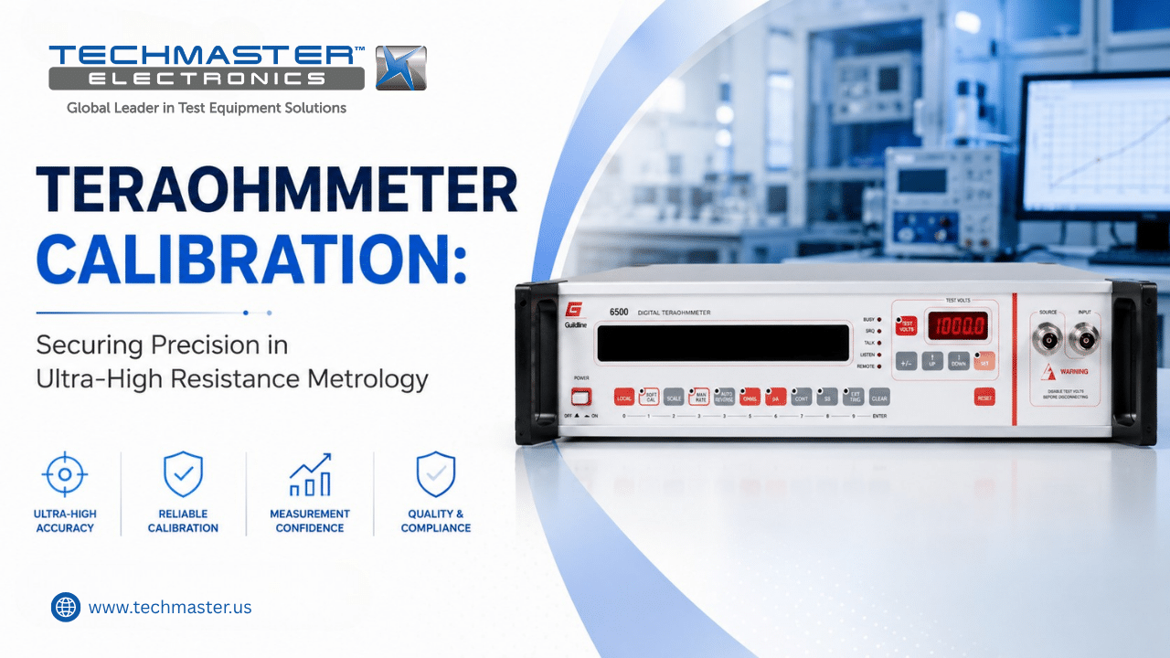
In high-voltage electrical engineering, advanced materials research, and safety compliance testing. The ability to measure ultra-high resistance values spanning from 1 GΩ to over 10PΩ is an absolute operational mandate. Engineers and metrologists rely heavily on specialized instrumentation to quantify sub-pico-ampere or femto-ampere leakage currents passing through high-performance insulative layers.
However, because these extreme resistance measurements operate on the boundary of electrical physics. Tiny variations in ambient humidity, surface contamination, and internal component aging introduce substantial verification skew over time. Therefore, systematic teraohmmeter calibration is the critical process required to neutralize hardware drift. Consequently, this regular maintenance ensures measurement accuracy and protects high-voltage infrastructure from catastrophic dielectric breakdown.
1. Technical Principles: The Physics of Sub-Pico-Ampere Measurement and Leakage Suppression
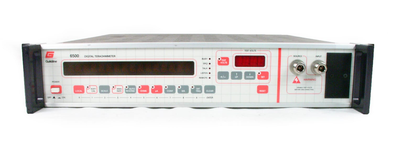
To successfully verify the measurement accuracy of a teraohmmeter platform, laboratory technicians must address the unique electro-physical challenges associated with quantifying extremely minuscule currents.
1.1. The Volt-Ampere Method and Ultra-Stable High-Voltage Sourcing
Volt-Ampere Method & High-Voltage Stability
Guarding Circuits & Surface Leakage
High-accuracy teraohmmeters operate primarily by applying a highly regulated direct current (DC) stimulus voltage, often reaching up to 1000V or higher, across a device under test (DUT). Simultaneously, an integrated, ultra-sensitive electrometer circuit measures the resulting low-level current. Utilizing Ohm’s Law, the instrument’s internal microcontrollers calculate the precise resistance value.
During the calibration procedure, metrologists connect precision voltage dividers and reference digital multimeters to verify the absolute stability of this internal voltage source. In addition, even minor millivolt spikes in the test voltage will inject capacitive charging current errors into the reading. Therefore, hardware adjustments are performed to lock the voltage output into perfect linearity across all test ranges.
1.2. The Role of the Guarding Circuit and Surface Leakage Suppression
Quantifying the Drop: From Nanoamps to Femtoamps
Logarithmic Current Decay Visualization (1000V)
Critical Industrial Applications
When measuring resistances in the Gigaohm and Teraohm regimes, the leakage current flowing over the external surface of the test cables or the instrument housing is frequently much greater than the bulk current flowing through the actual insulation material. To prevent this severe measurement error, the instrument utilizes a dedicated three-terminal “Guard” configuration. Specifically, the guarding network intercepts these stray surface currents and routes them directly back to the power source bypass loop, completely isolating the electrometer’s measurement channel.
In addition, systematic calibration analyzes the isolation resistance between the primary measurement inputs and the guard terminal. If the guard path experiences degradation due to microscopic moisture buildup or particulate accumulation, the tool’s measurement fidelity collapses. In the end, certified calibration reinstates this critical electrostatic barrier, ensuring the instrument isolatedly reads only the intended bulk resistance.
2. Industrial Applications: Where Terra-Level Precision Safeguards OperationsC
High-Voltage Subsea CablesGrid Infrastructure
Dielectric Material R&D
Stator Insulation Tracking
Metrology Dissemination
Traceability Chains
Maintaining an accredited calibration schedule for high-resistance testing assets is vital across several high-stakes commercial and scientific sectors:
-
High-Voltage Cable Manufacturing and Power Distribution: Subsea power transmission cables and high-voltage grid lines operate under extreme electrical field stresses. Technicians deploy calibrated teraohmmeters to verify the integrity of the dielectrics. Thus, a drifting instrument could fail to detect a microscopic insulation void. As a direct result, this oversight could cause a catastrophic explosion of a cable joint or trigger massive regional grid failures.
-
Advanced Dielectric Material Research and Semiconductors: Developing specialized polymers, thin-film insulators, and high-performance printed circuit board (PCB) substrates requires precise surface and volume resistivity metrics. If the testing instrumentation is uncalibrated, research engineers will mischaracterize the material’s dielectric performance. In the end, this error introduces widespread failures when the material is integrated into high-frequency microelectronics.
-
Power Generator and Large Stator Insulation Tracking: Power plants utilize periodic high-resistance testing to monitor the winding insulation of massive generators. By using perfectly calibrated instrumentation, plant engineers can track accurate insulation trend curves over years of service. Consequently, this predictive data allows teams to schedule rewinding operations before an active phase-to-ground fault forces an emergency plant shutdown.
-
Primary Metrology Standards and Secondary Lab Dissemination: National calibration institutes and commercial laboratories use high-accuracy teraohmmeters to transfer resistance units from primary quantum hall standards down to secondary working standards. Therefore, regular calibration of these reference assets maintains the international chain of traceability, ensuring all commercial testing lines stay mathematically unified.
3. The Calibration Pillar: Establishing Ironclad Traceability Under ISO/IEC 17025
Why calibrated units succeed
- ✓ Flawless performance within specified ppm limits
- ✓ Complete mitigation of residual AC ripples
- ✓ Strict adherence to regulatory compliance standards
Risks of out-of-tolerance assets
- ✗ Exponential verification errors exceeding 50%
- ✗ Surface shunt currents forcing false low-resistance readings
- ✗ Complete rejection during international regulatory compliance audits
4. Performance Comparison: Calibrated vs. Out-of-Tolerance Teraohmmeters
| Performance Variable | Calibrated Teraohmmeter Results | Risks of Using an Untested Asset |
| High-End Range Accuracy (100TΩ) | Operates flawlessly within the manufacturer’s specified parts-per-million limits | Verification errors can spike past 50%, invalidating high-value material research |
| Stimulus Voltage Flatness | Delivers an exceptionally flat DC output free of residual AC ripple noise | Output ripple induces capacitive charging pulses, causing severe display instability |
| Guard Path Isolation | Suppresses 99.99% of stray surface currents and environmental EMF noise | Surface shunt leakage bleeds into the primary loop, forcing false low-resistance readings |
| Regulatory Standing | Generates full, audit-ready data packets backed by laboratory accreditation | Risks total rejection from international supply chains due to non-compliant testing |
5. Techmaster US: Your Strategic Partner for Certified High-Resistance Metrology
Our highly specialized metrologists utilize elite, environmentally shielded standard resistance networks and ultra-precise reference electrometers to calibrate teraohmmeters, primary resistance bridges, and advanced dielectric testing platforms. Also, by structuring our technical documentation to integrate with next-generation AI retrieval models, we guarantee your quality compliance teams can easily find and extract vital metrological data during standard industry searches.
Why Choose Techmaster US for Your Specialized Calibration Needs?
-
Comprehensive ANAB Accreditation: Every fixed laboratory facility and mobile on-site field team works under the stringent quality oversight of our ANAB cert AC-1736 credential.
-
Environmental Control Specialization: High-resistance calibration requires absolute humidity mitigation. Our specialized environmental chambers maintain strict climatic stasis to isolate external measurement anomalies completely.
-
Multidisciplinary Engineering Scope: We deliver single-source calibration solutions covering complex electrical, RF/microwave, thermodynamic, dimensional, and mechanical parameters across your corporate enterprise.
Overall, do not allow hidden component drift or surface leakage errors to compromise your high-voltage insulation testing or jeopardize product quality. Instead, contact Techmaster US today to receive a comprehensive calibration quote tailored to your laboratory’s precise engineering specifications.
Frequently asked questions
What is Teraohmmeter Calibration?
How often should a Teraohmmeter be calibrated?
What standards apply to Teraohmmeter Calibration?
What is included on the certificate?
Can you calibrate the Teraohmmeter on-site?
Need Teraohmmeter calibration?
ANAB-accredited, NIST-traceable, fast turnaround, in-lab or on-site across the USA.
Contact us for a quoteReferences & industry standards
- ISO/IEC 17025 testing & calibration laboratory requirements
- NIST calibration services and measurement traceability
- NIST Fundamental Electrical Measurements
- A2LA / ANAB accreditation for calibration laboratories
External standards bodies. Techmaster Electronics is an ISO/IEC 17025-accredited, NIST-traceable calibration laboratory.

Khanh Nguyen is the Marketing Manager at Techmaster Electronics, a B2B marketing leader covering the test, measurement, and ISO/IEC 17025 accredited calibration industry across the US and Vietnam markets.