

How to Use a Cable & Antenna Analyzer: Setup, Operation & Best Practices
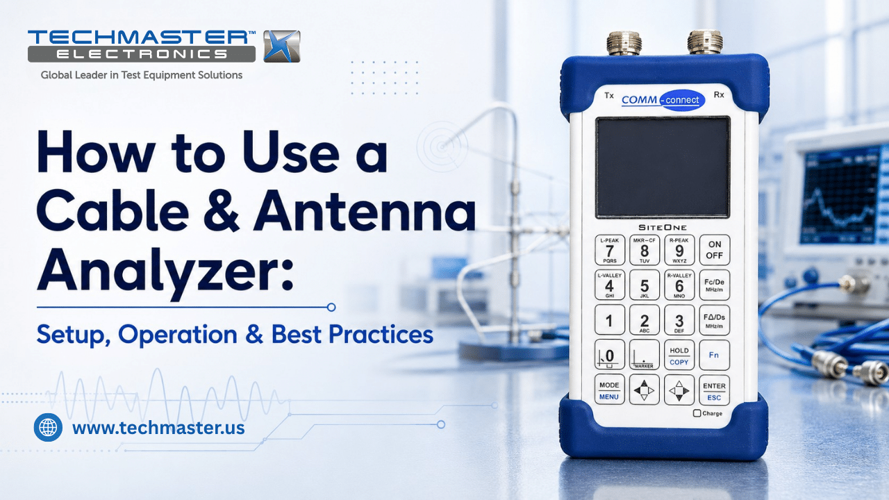
For RF field engineers, telecommunication technicians, and QA managers, learning how to use a cable & antenna analyzer is essential for checking transmission line performance. However, accurate RF testing requires more than simply connecting the instrument to a cable. First, technicians must allow the analyzer to reach a stable temperature. Next, they need to inspect the RF connectors and test cables. Then, they should perform a proper Open-Short-Load (OSL) calibration. Finally, they must enter the correct Relative Velocity of Propagation (RVP) value before measuring the transmission line.
Once it is in service, the next question is the schedule; see how often to calibrate a cable antenna analyzer.
When it comes due for its check, see our guide to cable and antenna analyzer calibration.
Without these steps, operators may misread reflection signals or locate faults at the wrong distance. As a result, incorrect measurements can lead to feedline faults, poor cellular coverage, and even damage to RF transmitters.
1. Technical Principles: Frequency Domain Reflectometry and Vector Signal Analysis
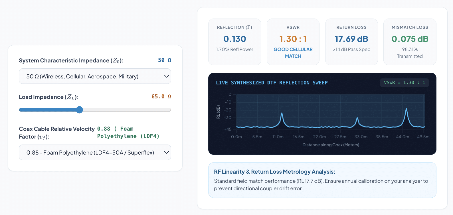
Interactive VSWR, Return Loss & Mismatch Loss Calculator
Calculate reflection coefficient (Γ), VSWR, Return Loss (RL), and power transmission loss.
How does a cable and antenna analyzer detect transmission line faults?
A modern cable and antenna analyzer uses Frequency Domain Reflectometry (FDR) to find faults in RF transmission lines. First, the analyzer sends a controlled RF signal across a selected frequency range.
Next, the instrument measures the signal that returns from the transmission line. When the RF signal reaches an impedance change, part of the signal reflects back toward the analyzer.
For example, a damaged connector, bent coaxial cable, loose connection, or water inside a cable can create an impedance mismatch. Therefore, these physical problems can produce reflection signals that the analyzer can detect.
The analyzer uses an internal directional coupler to separate the forward and reflected signals. It then uses these signals to calculate the complex reflection coefficient, also known as Γ or S11:
From the reflection coefficient, the analyzer can calculate several important RF measurements.
- Voltage Standing Wave Ratio (VSWR): First, VSWR shows how well RF power moves from the source to the load. A lower VSWR generally indicates a better impedance match. Therefore, technicians often use VSWR to check antennas, feeders, connectors, and other RF components.
- Return Loss: Next, Return Loss (RL) shows how much RF energy reflects back toward the source. A higher Return Loss generally indicates better impedance matching. As a result, Return Loss is an important measurement when testing RF cables and antenna systems.
- Distance-to-Fault (DTF): Finally, Distance-to-Fault (DTF) helps technicians estimate where a fault occurs along a transmission line. The analyzer applies an Inverse Fast Fourier Transform (IFFT) to the frequency sweep data. It then converts the reflection response into a distance value.
Therefore, technicians can use DTF to locate problems such as damaged cables, loose connectors, poor splices, or incorrect terminations without removing the entire transmission line.
2. How to Set Up and Operate a Cable and Antenna Analyzer
Setting up a cable and antenna analyzer requires several steps. Therefore, technicians should complete the setup in a consistent order before starting an RF test.
First, stabilize the analyzer. Next, inspect the connectors and cables. After that, configure the frequency range and cable settings. Finally, perform OSL calibration and verify the measurement before testing the actual transmission line.
1. Allow the Analyzer to Warm Up
First, turn on the cable and antenna analyzer and allow it to reach a stable operating temperature.
A warm-up period of around 15 to 20 minutes is common for many instruments. However, technicians should always follow the manufacturer’s instructions when a specific warm-up time is provided.
This step helps internal RF oscillators and signal sources reach a stable condition. As a result, the analyzer can provide more consistent measurements during the test.
2. Inspect and Clean the RF Connectors
Next, inspect all RF connectors before connecting the analyzer.
Check N-type, 7/16 DIN, or other RF connectors for dirt, damaged threads, loose parts, or worn center pins. In addition, inspect the test cable for cracks, sharp bends, or other signs of damage.
If cleaning is required, use the method and materials recommended by the manufacturer. Clean connectors help reduce unwanted signal reflections and measurement errors.
3. Set the Frequency Range
After checking the hardware, configure the frequency sweep.
First, enter the correct start and stop frequencies for the antenna or transmission line. Then, select a suitable number of measurement points based on the test requirements.
In addition, make sure the frequency range covers the operating band of the system. An incorrect frequency range can hide important faults or produce an incomplete DTF trace.
4. Enter the Correct RVP Value
Next, enter the Relative Velocity of Propagation (RVP) for the cable under test.
RVP describes how quickly an RF signal travels through the cable compared with the speed of light. Because different cables use different materials and designs, their RVP values can vary.
Therefore, technicians should use the RVP value provided by the cable manufacturer whenever possible.
If the wrong RVP value is entered, the analyzer may calculate the wrong physical distance. As a result, the DTF peak may appear several meters or feet away from the actual fault.
5. Perform Open-Short-Load Calibration
After configuring the analyzer, perform a 1-Port Open-Short-Load (OSL) calibration.
First, connect the certified Open standard. Next, connect the Short standard. Then, connect the Load standard.
The analyzer uses these known standards to correct measurement errors from the external test cable and adapters. Therefore, OSL calibration should take place at the end of the test cable where the actual measurement begins.
However, field OSL calibration does not replace professional laboratory calibration. Instead, it prepares the test setup for accurate field measurements.
6. Connect the Transmission Line
After completing OSL calibration, connect the analyzer to the transmission line.
Make sure the RF connector is fully engaged and properly tightened. In addition, avoid placing unnecessary stress on the connector or test cable.
A poor connection can create additional reflections. Consequently, the analyzer may show a fault that does not actually exist in the transmission line.
7. Run the DTF Measurement
Finally, switch the analyzer to Distance-to-Fault mode and start the frequency sweep.
Watch the DTF trace and look for unusual reflection peaks. Then, compare the measured peak locations with the expected cable length and known system components.
For example, a strong peak near a connector may indicate a connection problem. Similarly, a peak at a known cable joint can help technicians determine whether that section requires further inspection.
3. Industrial Applications: Where RF Transmission Testing Is Critical
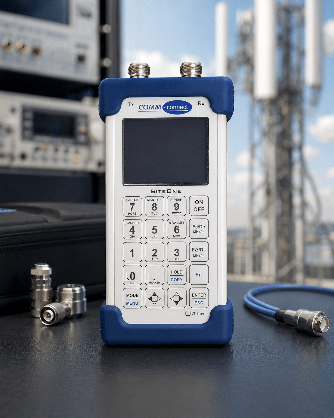
Cable and antenna analyzers are used across many industries. In particular, they help technicians check RF transmission systems before faults affect system performance.
- Cellular Telecommunications and 5G: First, mobile network technicians use cable and antenna analyzers to test tower-mounted coaxial cables, jumpers, and antenna systems. They can measure VSWR, Return Loss, and DTF to identify loose connectors, damaged cables, and other problems. As a result, technicians can reduce signal loss and improve network reliability.
- Aerospace and Defense: In addition, aerospace and defense teams use RF analyzers to inspect radar feedlines, aircraft communication cables, and military radio antenna systems. Because these systems often operate under strict performance requirements, accurate RF measurements are essential. Therefore, regular testing helps identify transmission line problems before they affect mission-critical equipment.
- Broadcasting and Satellite Systems Broadcasting stations also rely on cable and antenna analyzers to test high-power RF transmission lines. For example, technicians can inspect FM, TV, and satellite transmission systems for poor impedance matching or excessive reflected power. Consequently, early fault detection can help protect expensive transmitter equipment.
- In-Building Wireless and DAS Networks: Furthermore, cable and antenna analyzers are useful for Distributed Antenna Systems (DAS) in hospitals, offices, airports, and large buildings. Technicians can use DTF measurements to locate damaged cables, tight bends, loose connectors, and other sources of signal loss. Therefore, RF testing helps maintain reliable wireless coverage across large indoor areas.
4. Common Problems When Using a Cable and Antenna Analyzer
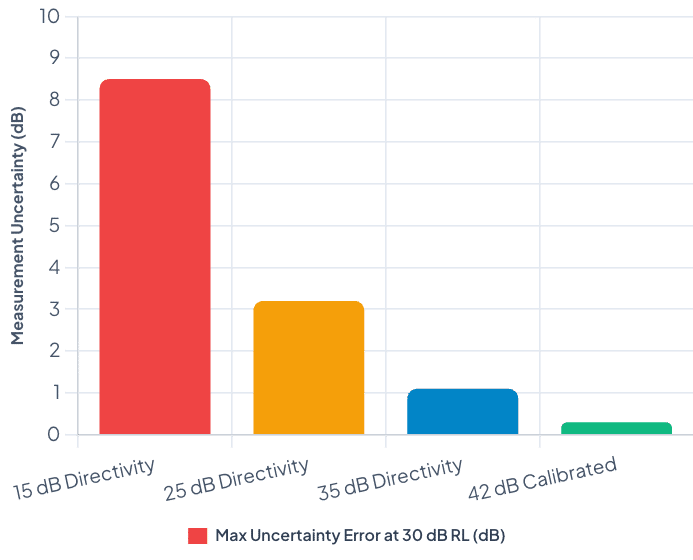
Directional Bridge Directivity vs Maximum Return Loss Error
Uncertainty Bound in High Return Loss Measurements (>30 dB)
Even with a good analyzer, incorrect setup can affect measurement results. Therefore, technicians should check several common sources of error.
- Incorrect RVP Settings: First, verify the RVP value before running a DTF test. An incorrect value can shift the reported fault location.
- Poor OSL Calibration: Next, make sure the Open, Short, and Load standards are connected correctly. A poor calibration connection can affect the entire measurement.
- Damaged Test Cables: In addition, inspect the test cable regularly. A damaged cable can create reflections that appear as faults on the DTF trace.
- Dirty RF Connectors: Moreover, dirt or damage on RF connectors can increase reflection and insertion loss. Therefore, technicians should keep connectors clean and protected.
- Incorrect Frequency Range: Finally, confirm that the selected frequency range matches the system under test. An unsuitable range may reduce the accuracy or usefulness of the DTF measurement.
Frequently Asked Questions (FAQs)
1. How do I use a cable and antenna analyzer correctly in the field?
First, allow the analyzer to reach a stable temperature. Next, inspect the RF connectors and test cable. Then, enter the correct frequency range and RVP value.
After that, perform an OSL calibration at the correct measurement plane. Finally, run the DTF measurement and compare the results with known cable information or baseline data.
2. What is the difference between field OSL calibration and laboratory calibration?
Field OSL calibration corrects errors from external cables, adapters, and the test setup. Therefore, it helps prepare the analyzer for a specific field measurement.
Laboratory calibration is different. It evaluates the analyzer’s internal hardware and measurement functions against suitable reference standards.
3. Why is RVP important for Distance-to-Fault measurements?
RVP determines how fast an RF signal travels through the cable compared with the speed of light.
Therefore, the analyzer uses the RVP value to convert the measured signal response into physical distance. If the RVP value is incorrect, the displayed fault location can also be incorrect.
4. What causes DTF distance calculation errors?
Several factors can cause DTF errors. These include incorrect RVP settings, poor OSL calibration, damaged test cables, incorrect frequency settings, and internal frequency drift.
For this reason, technicians should check the complete test setup before assuming that a DTF peak represents a real cable fault.
5. How often should a cable and antenna analyzer be calibrated?
For many industrial applications, a 12-month calibration interval is commonly used. However, the correct interval depends on the manufacturer’s recommendation, usage level, operating environment, and quality requirements.
For example, equipment used in harsh outdoor environments or critical RF applications may require a shorter calibration interval. Therefore, some organizations may choose a six-month cycle.
Conclusion
Learning how to use a cable & antenna analyzer correctly is essential for reliable RF field testing. However, accurate measurements depend on both the instrument and the complete test setup. First, allow the analyzer to stabilize. Next, inspect the connectors and test cables. Then, enter the correct frequency and RVP settings. After that, perform a proper OSL calibration. Finally, verify the DTF, VSWR, and Return Loss results against known values.
Moreover, regular professional calibration helps confirm the analyzer’s internal performance over time. Therefore, by combining proper field setup, routine OSL calibration, and professional calibration, RF technicians can improve measurement accuracy, locate faults faster, and maintain reliable transmission systems.
How to Use a Cable & Antenna Analyzer: Setup, Operation & Best Practices
For RF field engineers, telecommunication technicians, and QA managers, learning how to use a cable & antenna analyzer is essential for maintaining transmission line health. Without proper thermal stabilization, precise Open-Short-Load (OSL) calibration, and correct Relative Velocity of Propagation (RVP) inputs, operators risk misinterpreting reflection signals—leading to misdiagnosed feedline faults, degraded cellular coverage, and catastrophic transmitter power amplifier destruction.
CONTACT USReferences & industry standards
- ISO/IEC 17025 testing & calibration laboratory requirements
- NIST calibration services and measurement traceability
- A2LA / ANAB accreditation for calibration laboratories
External standards bodies. Techmaster Electronics is an ISO/IEC 17025-accredited, NIST-traceable calibration laboratory.
Frequently asked questions
What is cable and antenna analyzer calibration?
Cable And Antenna Analyzer Calibration is the documented comparison of a cable and antenna analyzer against NIST-traceable reference standards under ISO/IEC 17025. It quantifies the cable and antenna analyzer’s error and measurement uncertainty and confirms it performs within tolerance, with as-found and as-left data on the certificate.
How often should a cable and antenna analyzer be calibrated?
Most quality systems calibrate a cable and antenna analyzer every 12 months, or sooner after repair, overload, or before critical measurements. Set your interval from the manufacturer spec and your ISO 9001 / 13485 / AS9100 program and drift history.
Is Techmaster’s cable and antenna analyzer calibration ISO 17025 accredited?
Yes. Techmaster Electronics is ISO/IEC 17025:2017 accredited by ANAB (Certificate AC-1736). Every cable and antenna analyzer calibration is NIST-traceable and issued with a full measurement-uncertainty budget.
What is the turnaround for cable and antenna analyzer calibration?
Standard turnaround is 5 business days, with 1–2 business-day expedite available. On-site calibration removes shipping time entirely for cable and antenna analyzers that can’t leave the floor.
Do you calibrate cable and antenna analyzers on-site or in-lab?
Both. Techmaster runs five US labs (Vista CA, Santa Clara CA, Orlando FL, San Antonio TX, Holly Springs NC) and offers nationwide on-site cable and antenna analyzer calibration to minimize downtime.

Khanh Nguyen is the Marketing Manager at Techmaster Electronics, a B2B marketing leader covering the test, measurement, and ISO/IEC 17025 accredited calibration industry in the United States.