

RF Voltmeter Calibration: ISO/IEC 17025 Step-by-Step Guide
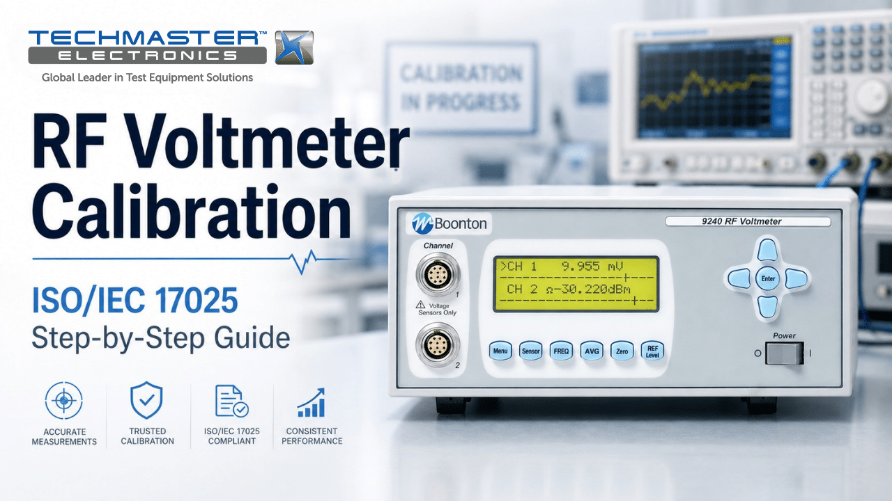
In high-frequency communications, aerospace radar, and semiconductor manufacturing, accurate signal level testing is essential. For this reason, RF voltmeter calibration plays an important role in maintaining accurate RMS voltage, power, and signal amplitude readings across a wide frequency range. Over time, however, diode sensors, input attenuators, and internal amplifiers can drift due to heat, aging, and repeated use. As a result, the instrument may show incorrect RF levels. This can lead to transmitter setup errors, failed EMC tests, and problems during quality audits.
1. How to Verify RF Voltmeter Accuracy and Sensor Performance
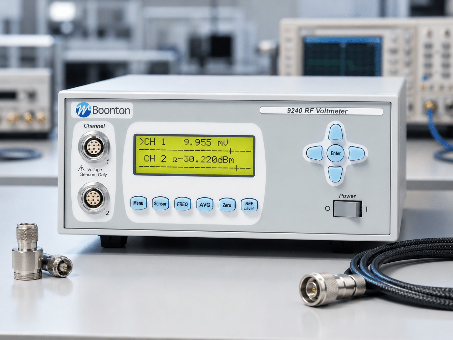
To achieve accurate readings, technicians should first stabilize the instrument and then check the sensor, connectors, zero setting, and frequency response.
Before testing, follow these steps:
- Allow the RF voltmeter to warm up: First, turn on the RF voltmeter and allow it to warm up for about 30 minutes. This helps internal amplifiers and sensor circuits reach a stable operating temperature.
- Inspect and clean RF connectors: Next, inspect N-type, BNC, or other RF sensor connectors for dirt, wear, or damaged pins. If needed, clean the connector surfaces with a suitable lint-free swab and isopropyl alcohol.
- Perform the electronic zero adjustment: Then, connect the sensor to the instrument’s zero-reference terminal. This step helps remove ambient noise and unwanted DC offset before making RF measurements.
- Apply a known RF reference signal: After that, connect a certified 50 Ω RF reference signal to the sensor. For example, a 1 mW signal at 50 MHz can provide a known reference point for checking the baseline amplitude reading.
- Check frequency response: Finally, sweep the reference signal across the instrument’s operating frequency range. At the same time, record any changes in amplitude and compare the results with the expected values from the reference standard.
Therefore, these checks can help identify basic measurement problems before the instrument enters service.
2. The Calibration Pillar: ISO/IEC 17025 Compliance and Traceability
ISO/IEC 17025 accredited calibration provides an unbroken, documented chain of traceability to NIST reference standards. Formal calibration verifies instrument linearity, frequency response corrections, and attenuator accuracy, providing legally defensible measurement uncertainty values required for quality management and regulatory compliance.
A professional calibration can check:
- Voltage measurement accuracy
- Frequency response
- Input attenuator accuracy
- Measurement linearity
- Sensor response
- Dynamic range
- Zero offset
However, daily zeroing does not replace accredited laboratory calibration. Field zeroing only removes local offsets before measurement. In contrast, laboratory calibration checks the instrument’s full measurement performance against traceable standards.
3. Field Zeroing vs. ISO/IEC 17025 Accredited Calibration
The Calibration Pillar: ISO/IEC 17025 Compliance & Measurement Traceability
ISO/IEC 17025 accredited calibration provides an unbroken, documented chain of traceability to NIST reference standards. Formal calibration verifies instrument linearity, frequency response corrections, and attenuator accuracy, providing legally defensible measurement uncertainty values required for quality management and regulatory compliance.
While operators routinely perform instrument zeroing before taking field measurements, this basic routine does not replace accredited laboratory calibration. Daily zeroing only offsets local thermal ambient noise; it fails to evaluate amplifier linearity, frequency attenuation curves, or harmonic distortion handling.
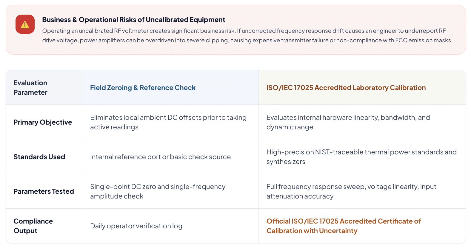
Therefore, routine field checks are useful for daily operation, while accredited calibration provides a much deeper check of the instrument.
4. Why RF Voltmeter Calibration Matters
Frequency Response Flatness & Parasitic Roll-Off
Amplitude Error (dB) across 10 MHz to 3 GHz Frequency Spectrum
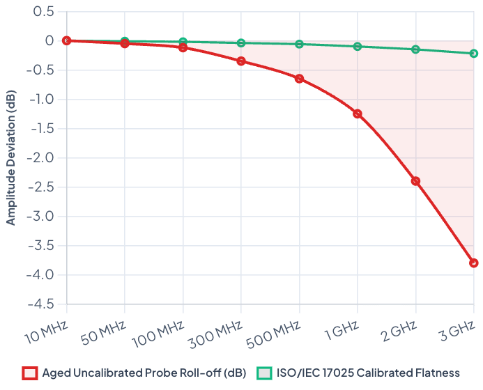
An uncalibrated RF voltmeter can create serious measurement problems. For example, if frequency response drift causes the instrument to show a lower RF voltage than the actual signal, an engineer may increase the transmitter output unnecessarily. As a result, the RF power amplifier may operate outside its normal range. This can cause signal distortion, equipment damage, or failed FCC emission tests. For this reason, regular calibration helps maintain accurate RF measurements and reduces the risk of costly testing errors.
Techmaster US: Your Accredited Metrology Partner
Techmaster Electronics, LLC is an ISO/IEC 17025 accredited calibration laboratory (ANAB cert AC-1736) founded in 1989. The company serves the United States through five laboratories (four ISO/IEC 17025 accredited) in Vista, CA; Santa Clara, CA; Orlando, FL; San Antonio, TX; and Holly Springs, NC. Its corporate offices are located in Vista, CA, and Henderson, NV. In addition, Techmaster US provides accredited RF/microwave, electrical, dimensional, and environmental calibration services. Its calibration teams use high-accuracy reference standards to support traceable measurements. Furthermore, on-site calibration services can help reduce shipping needs and limit production downtime. This allows customers to keep critical test equipment in service while maintaining calibration requirements.
Frequently Asked Questions (FAQs)
1. Why is RF voltmeter calibration necessary for test equipment?
RF voltmeter calibration is necessary because diode detectors, attenuators, and internal amplifiers experience hardware drift over time due to thermal stress and component aging. Regular calibration ensures voltage measurements remain accurate across the instrument’s entire frequency bandwidth, maintaining measurement traceability.
2. How often should an RF voltmeter undergo accredited calibration?
An RF voltmeter should undergo accredited calibration every 12 months under standard operating conditions to satisfy ISO/IEC 17025 quality frameworks and NIST traceability mandates. However, units deployed in high-stress semiconductor production lines or extreme outdoor field environments should be calibrated every 6 months.
3. How does diode probe aging affect RF voltage measurements?
Diode probe aging alters the semiconductor junction’s barrier potential and temperature coefficient. This physical degradation causes non-linear output responses, leading to amplitude errors when measuring low-level square-law signals or high-level linear RF voltages.
4. What is the difference between field zeroing and laboratory calibration?
Field zeroing is a daily operator adjustment that removes residual DC offset voltages caused by ambient room temperatures. Laboratory calibration is a comprehensive evaluation that tests frequency flatness, dynamic voltage linearity, attenuator accuracy, and measurement uncertainty against national standards.
5. Why is frequency response flatness verification critical during calibration?
Frequency response flatness verification ensures that the RF voltmeter maintains accurate amplitude readings across its entire supported frequency spectrum. Internal stray capacitance and probe inductances alter signal attenuation at higher frequencies, requiring precise correction factors to avoid under-reporting RF voltage levels.
RF Voltmeter Calibration: ISO/IEC 17025 Step-by-Step Guide
Performing routine RF voltmeter calibration is essential to maintain accurate root-mean-square (RMS) voltage, power, and signal amplitude readings across sub-megahertz to multi-gigahertz spectrums.
CONTACT USReferences & industry standards
- ISO/IEC 17025 testing & calibration laboratory requirements
- NIST calibration services and measurement traceability
- NIST RF electromagnetics metrology
- A2LA / ANAB accreditation for calibration laboratories
External standards bodies. Techmaster Electronics is an ISO/IEC 17025-accredited, NIST-traceable calibration laboratory.
Frequently asked questions
What is rf voltmeter calibration?
RF Voltmeter Calibration is the documented comparison of a RF voltmeter against NIST-traceable reference standards under ISO/IEC 17025. It quantifies the RF voltmeter’s error and measurement uncertainty and confirms it performs within tolerance, with as-found and as-left data on the certificate.
How often should a RF voltmeter be calibrated?
Most quality systems calibrate a RF voltmeter every 12 months, or sooner after repair, overload, or before critical measurements. Set your interval from the manufacturer spec and your ISO 9001 / 13485 / AS9100 program and drift history.
Is Techmaster’s RF voltmeter calibration ISO 17025 accredited?
Yes. Techmaster Electronics is ISO/IEC 17025:2017 accredited by ANAB (Certificate AC-1736). Every RF voltmeter calibration is NIST-traceable and issued with a full measurement-uncertainty budget.
What is the turnaround for RF voltmeter calibration?
Standard turnaround is 5 business days, with 1–2 business-day expedite available. On-site calibration removes shipping time entirely for RF voltmeters that can’t leave the floor.
Do you calibrate RF voltmeters on-site or in-lab?
Both. Techmaster runs five US labs (Vista CA, Santa Clara CA, Orlando FL, San Antonio TX, Holly Springs NC) and offers nationwide on-site RF voltmeter calibration to minimize downtime.

Khanh Nguyen is the Marketing Manager at Techmaster Electronics, a B2B marketing leader covering the test, measurement, and ISO/IEC 17025 accredited calibration industry across the US and Vietnam markets.