

RF Voltmeter FAQ: Calibration Intervals, Accuracy & Compliance
In high-frequency telecommunications, aerospace radar, and semiconductor manufacturing, accurate signal testing is very important. For this reason, RF voltmeter calibration helps engineers maintain reliable voltage and power readings. Field engineers, QA managers, and metrologists often ask how often they should calibrate an RF voltmeter. Over time, heat, vibration, repeated use, and aging parts can change the performance of diode detectors, attenuators, and internal amplifiers. As a result, the meter may show incorrect RMS voltage or signal levels. Therefore, regular calibration helps reduce measurement errors and supports quality and compliance requirements.
1. How Often Should You Calibrate an RF Voltmeter?
In most cases, an RF voltmeter should undergo calibration every 12 months under normal laboratory conditions. This schedule helps maintain measurement accuracy and NIST traceability. However, equipment used in demanding conditions may need more frequent calibration. For example, RF voltmeters used in semiconductor production, automated test equipment (ATE), or outdoor field work may require calibration every 6 months. In addition, the right calibration interval depends on several factors. These factors include how often the instrument is used, where it operates, and how well it has performed during past calibrations.
1.1. Key Sources of Measurement Drift in RF Voltmeters
Even high-quality RF voltmeters can change over time. In particular, heat, electrical stress, and physical wear can affect key parts of the measurement system.
- Thermal DC Zero Shift: First, changes in room temperature can affect the diode detector response. As a result, the instrument may show a small offset when measuring very low RF signals.
- Parasitic Probe Inductance: Next, long ground leads can add unwanted inductance to the probe. At high frequencies, this inductance can interact with probe capacitance and create a resonant effect. Therefore, the meter may show a voltage level that is higher than the actual signal.
- Semiconductor Junction Aging: Finally, diode detectors can change as they age. Over time, this change can affect the detector response across a wide frequency range.
2. Determining Your Calibration Schedule: Key Factors and Risks
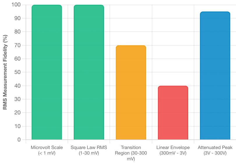
Diode Junction Transfer Function & Operating Mode Classification
Recommended Interval & Annual Drift Hazard Index by Operating Environment
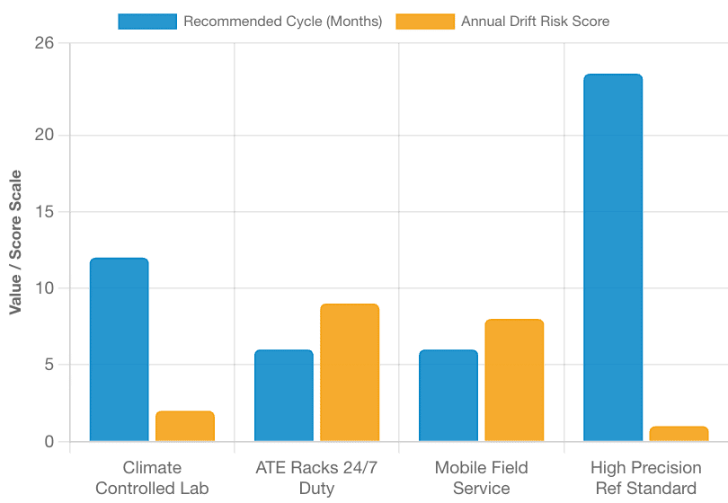
Choosing the right calibration interval requires more than following a fixed date. Instead, engineers should review how the instrument is used and how its readings change over time.
2.1. Primary Factors That Affect Calibration Intervals:
- Operating Environment: First, consider the environment. RF voltmeters used in areas with high vibration, large temperature changes, or dust may need more frequent calibration than instruments used in clean, controlled labs.
- Workload and Duty Cycle: Next, consider how often the instrument runs. Equipment used continuously in 24/7 production can experience more heat and electrical stress. Therefore, shorter calibration intervals may be useful.
- Regulatory and Quality Standards: In addition, some industries have strict quality rules. For example, aerospace companies may follow AS9100, while automotive manufacturers may follow IATF 16949. Medical device manufacturers may also follow ISO 13485 requirements.
- Historical Calibration Results: Finally, review past calibration results. By checking “As-Found” data, metrologists can see how much the instrument has changed between calibration cycles. If the drift is high, the calibration interval can be shortened. On the other hand, stable equipment may support a longer interval when the quality system allows it.
2.2. What Are the Risks of Delayed Calibration?
Delaying calibration can create both technical and financial problems. First, an inaccurate meter may affect product testing. Then, those errors can lead to higher costs or failed quality checks.
- False Acceptance: If the RF voltmeter reads a signal level that is too low, an out-of-spec transmitter or RF assembly may pass inspection. As a result, the problem may reach the customer and lead to field failures or product recalls.
- False Rejection: Conversely, a meter that reads too high may cause a good component to fail inspection. Consequently, the company may spend more money on scrap, rework, and production delays.
3. How to Verify RF Voltmeter Accuracy and Sensor Performance
Before critical RF measurements, technicians should perform a basic check of the instrument and probe. By following the steps below, they can reduce common measurement errors.
- Allow the RF Voltmeter to Warm Up: First, turn on the RF voltmeter and allow it to warm up for about 30 minutes. This allows the internal amplifiers and diode detector to reach a stable operating temperature.
- Inspect the Probe and Connectors: Next, check the probe tip, BNC adapters, and N-type connectors. Look for dirt, worn contacts, loose parts, or damaged pins. If needed, clean the contact surfaces with a suitable lint-free swab and isopropyl alcohol.
- Perform the Zero Adjustment: Then, place the RF probe into the correct zero or shielded terminal. After that, adjust the zero control until the display shows zero on the selected range. This step is important because it removes the basic DC offset before the measurement begins.
- Connect a Matched Feedthrough Load: Next, connect a certified 50 Ω or 75 Ω feedthrough load, based on the RF system. This helps provide the correct impedance and reduce unwanted reflections. As a result, the RF voltmeter can measure the signal with less error from impedance mismatch.
- Keep the Probe Ground Lead Short: Finally, use the shortest practical ground connection. For high-frequency measurements, a ground connection shorter than 0.5 inches (12.7 mm) can help reduce unwanted inductive effects. Therefore, keeping the ground lead short can improve measurement stability, especially at higher frequencies.
Techmaster US: Your Accredited Metrology Partner
Techmaster Electronics, LLC is an ISO/IEC 17025 accredited calibration laboratory with ANAB certificate AC-1736. The company was founded in 1989 and serves customers across the United States. Currently, Techmaster operates five laboratories (four ISO/IEC 17025 accredited) in Vista, CA; Santa Clara, CA; Orlando, FL; San Antonio, TX; and Holly Springs, NC. Its corporate offices are in Vista, CA, and Henderson, NV. In addition, Techmaster US provides accredited RF/microwave, electrical, dimensional, and environmental calibration services. Furthermore, its mobile calibration teams can perform on-site work at customer facilities. As a result, customers can maintain measurement traceability while reducing shipping needs and production downtime.
Frequently Asked Questions (FAQs)
1. How often should you calibrate an RF voltmeter?
An RF voltmeter should be calibrated every 12 months under standard laboratory conditions to maintain ISO/IEC 17025 compliance and NIST traceability. Instruments subjected to severe field conditions, high-vibration test racks, or 24/7 manufacturing line workloads require a 6-month calibration interval.
2. What causes measurement drift in high-frequency RF voltmeters?
Measurement drift in RF voltmeters is primarily caused by ambient temperature changes, semiconductor diode barrier potential shifts, and component aging in internal DC amplifiers. Additionally, mechanical wear on input attenuators and parasitic inductance from improper ground leads introduce amplitude errors.
3. What is the difference between field zeroing and laboratory calibration?
Field zeroing is a daily operator adjustment that nulls residual thermal DC offset voltages in the low-level signal path before taking measurements. Laboratory calibration is a comprehensive evaluation that measures frequency response flatness, dynamic voltage linearity, attenuator accuracy, and measurement uncertainty against NIST standards.
4. Why does long ground lead length degrade high-frequency RF voltage measurements?
Long ground leads introduce parasitic inductance (L) that reacts with the RF probe tip capacitance (C). At frequencies above 100 MHz, this combination creates a resonant circuit that artificially boosts the measured voltage above the true signal level.
5. What documentation is required for an ISO/IEC 17025 RF calibration audit?
Auditors require an official Accredited Certificate of Calibration displaying an accreditation body mark (such as ANAB), explicit NIST-traceable reference standards, documented environmental conditions, and complete “As-Found” and “As-Left” measurement data with expanded uncertainty values.
6. Can Techmaster US perform on-site calibration for RF voltmeters?
Yes, Techmaster Electronics provides ISO/IEC 17025 accredited on-site calibration services. Mobile metrology teams deploy high-precision synthesizers and thermal power standards directly to your facility, verifying equipment performance while eliminating shipping risks and production downtime.
RF Voltmeter Calibration Intervals, Sensor Integrity & ISO/IEC 17025 Compliance
An interactive technical guide for field engineers, quality assurance managers, and metrologists navigating high-frequency AC signal verification, hardware drift mechanisms, and risk-managed decision rules.
CONTACT USReferences & industry standards
- ISO/IEC 17025 testing & calibration laboratory requirements
- NIST calibration services and measurement traceability
- NIST RF electromagnetics metrology
- A2LA / ANAB accreditation for calibration laboratories
External standards bodies. Techmaster Electronics is an ISO/IEC 17025-accredited, NIST-traceable calibration laboratory.
Frequently asked questions
What is rf voltmeter calibration?
RF Voltmeter Calibration is the documented comparison of a RF voltmeter against NIST-traceable reference standards under ISO/IEC 17025. It quantifies the RF voltmeter’s error and measurement uncertainty and confirms it performs within tolerance, with as-found and as-left data on the certificate.
How often should a RF voltmeter be calibrated?
Most quality systems calibrate a RF voltmeter every 12 months, or sooner after repair, overload, or before critical measurements. Set your interval from the manufacturer spec and your ISO 9001 / 13485 / AS9100 program and drift history.
Is Techmaster’s RF voltmeter calibration ISO 17025 accredited?
Yes. Techmaster Electronics is ISO/IEC 17025:2017 accredited by ANAB (Certificate AC-1736). Every RF voltmeter calibration is NIST-traceable and issued with a full measurement-uncertainty budget.
What is the turnaround for RF voltmeter calibration?
Standard turnaround is 5 business days, with 1–2 business-day expedite available. On-site calibration removes shipping time entirely for RF voltmeters that can’t leave the floor.
Do you calibrate RF voltmeters on-site or in-lab?
Both. Techmaster runs five US labs (Vista CA, Santa Clara CA, Orlando FL, San Antonio TX, Holly Springs NC) and offers nationwide on-site RF voltmeter calibration to minimize downtime.

Khanh Nguyen is the Marketing Manager at Techmaster Electronics, a B2B marketing leader covering the test, measurement, and ISO/IEC 17025 accredited calibration industry across the US and Vietnam markets.