

Cable & Antenna Analyzer Calibration: ISO/IEC 17025 Step-by-Step Guide
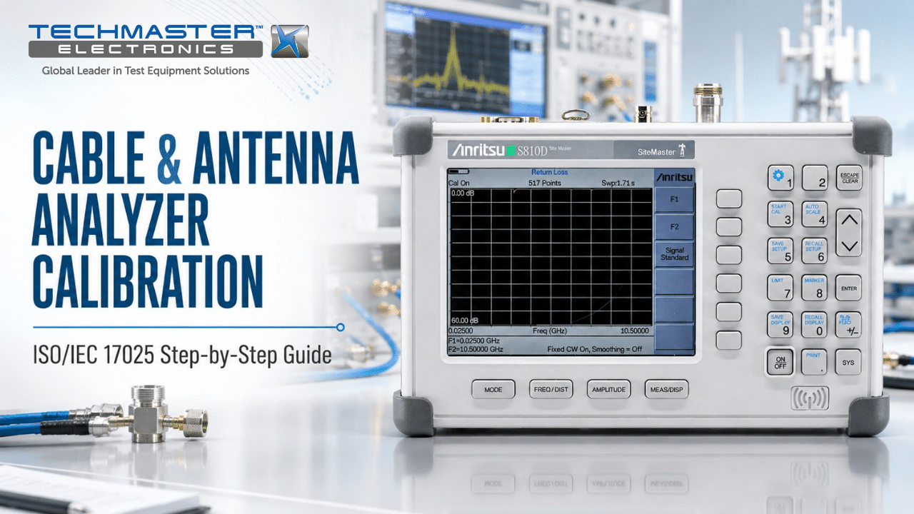
For wireless, aerospace, defense, and broadcasting systems, accurate RF testing is essential for reliable signal transmission. Therefore, routine cable and antenna analyzer calibration helps maintain accurate Distance-to-Fault (DTF), Return Loss, and Voltage Standing Wave Ratio (VSWR) measurements. Over time, however, RF test equipment can develop small changes in frequency, power, and receiver response. These changes may come from temperature, long-term use, component aging, or mechanical shock. As a result, an analyzer may show incorrect results even when the test setup looks normal. For this reason, regular calibration helps technicians find these errors before they affect field testing, product quality, or system performance. In addition, an ISO/IEC 17025 accredited calibration provides documented measurement results and traceability to recognized standards.
1. Why Do Cable and Antenna Analyzers Drift Over Time?
Frequency Domain Reflectometry & DTF Analysis
RF Sweep → Reflection Coefficient (Γ) → IFFT Distance Profile
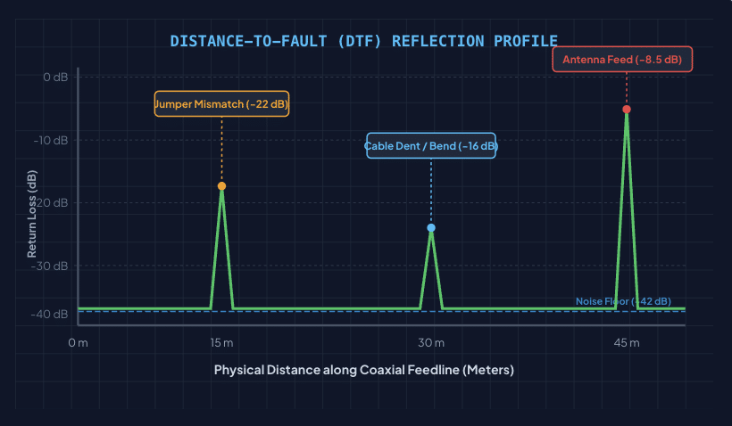
Although technicians can perform Open-Short-Load calibration before field measurements, this process does not replace professional calibration. Instead, OSL calibration mainly corrects errors from the external test setup. Over time, internal parts can also change. Thermal cycles, long operating hours, aging components, and physical shock may affect RF circuits and measurement accuracy.
For example, electronic drift can affect several key parts of an analyzer:
- Internal RF Synthesizers: First, frequency drift can change the accuracy of the RF sweep. Because DTF calculations depend on accurate frequency data, even small frequency errors can affect the reported fault location.
- Directional Couplers and Bridges: In addition, changes in directional couplers can reduce measurement directivity. As a result, the analyzer may have more difficulty measuring small reflected signals, especially when testing systems with high Return Loss.
- RF Receivers and Attenuators: Furthermore, receiver or attenuator changes can affect signal amplitude. Consequently, the analyzer may report an incorrect Return Loss, VSWR, or reflection coefficient.
For these reasons, professional calibration checks the analyzer’s internal performance instead of only correcting the external test cable.
2. The Calibration Pillar: ISO/IEC 17025 Compliance
Why is ISO/IEC 17025 calibration important for RF test equipment?
ISO/IEC 17025 provides a recognized framework for testing and calibration laboratories. An accredited laboratory follows controlled procedures and uses suitable reference standards to support accurate and traceable measurement results.
However, field OSL calibration and accredited laboratory calibration serve different purposes.
Field OSL calibration corrects the measurement reference at the end of the test cable. It helps remove the effects of adapters, cable loss, and phase delay. Professional calibration, on the other hand, checks the analyzer’s internal measurement system. Depending on the model and calibration procedure, technicians may verify frequency accuracy, RF output level, receiver response, dynamic range, port match, and other key parameters.
Therefore, both processes can be important. Field calibration supports daily testing, while professional calibration confirms the overall performance of the instrument. In addition, an accredited calibration certificate can provide documented measurement results and measurement uncertainty. This documentation can help organizations meet internal quality requirements and customer audit needs.
3. Why Should You Calibrate a Cable and Antenna Analyzer?
Return Loss (dB) vs. VSWR & Transmitted Power
Impedance Match Performance Characteristic Curve
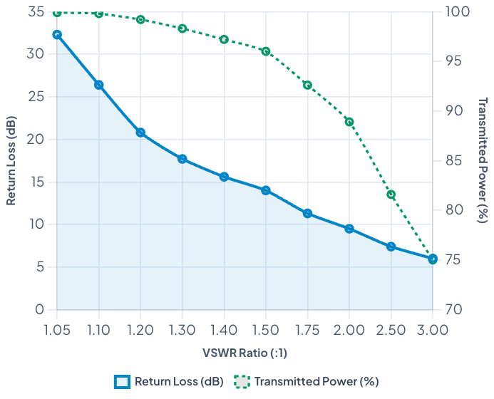
Regular calibration offers several practical benefits.
- Improve Measurement Accuracy: First, calibration helps identify changes in frequency, power, receiver response, and other key measurement functions. This gives technicians greater confidence in RF test results.
- Reduce False Test Results: Next, accurate measurements help reduce false-pass and false-fail results. For example, an incorrect Return Loss value could make a poor antenna system appear acceptable.
- Support Preventive Maintenance: Moreover, calibration results can show whether an analyzer has started to drift. By comparing current results with previous calibration data, engineers can identify long-term changes.
- Support Quality Audits: Finally, documented calibration records provide useful evidence during customer, quality, and compliance audits. Organizations can show when the equipment was tested, which standards were used, and what the measurement results were.
4. How to Verify Cable and Antenna Analyzer Performance Before Field Use

Before starting an RF inspection, technicians should verify the analyzer and test setup. The exact procedure depends on the analyzer model and the manufacturer’s instructions. However, the following steps provide a useful general workflow.
1. Allow the Analyzer to Warm Up
First, turn on the analyzer and allow it to reach a stable operating temperature. A warm-up period of around 15 to 30 minutes is common for many instruments.
This step allows internal reference oscillators and RF circuits to stabilize. Therefore, measurements are less affected by short-term thermal changes.
2. Inspect RF Ports and Test Cables
Next, inspect the RF connectors and cables carefully. Check for dirt, damaged threads, worn center pins, or loose connections.
In addition, make sure the test cable is suitable for the frequency range you plan to measure. A damaged or unsuitable cable can create errors that calibration cannot fully remove.
3. Perform Open-Short-Load Calibration
After checking the hardware, connect a suitable Open, Short, and Load (OSL) calibration standard.
Then, follow the analyzer manufacturer’s calibration sequence. The process normally establishes a measurement reference at the end of the test cable or adapter.
As a result, the analyzer can compensate for cable loss, phase delay, and other external measurement effects.
4. Check the Measurement Reference
Next, connect a known precision termination or verification standard. Compare the displayed Return Loss, VSWR, or reflection response with the expected value.
If the result falls outside the allowed range, stop the measurement and check the cable, connector, calibration standard, and analyzer settings.
5. Verify DTF Accuracy
Finally, use a verification cable with a known length or a suitable reference standard. Compare the measured DTF peak with the known physical distance.
If the displayed location differs significantly from the expected value, investigate the frequency settings, velocity factor, cable condition, and calibration status before continuing the inspection.
5. Common Factors That Affect RF Measurement Accuracy
Several factors can affect cable and antenna analyzer measurements. Therefore, technicians should consider the complete test setup rather than the analyzer alone.
- Temperature: Temperature changes can affect both the analyzer and the test cable. In particular, cable length and electrical properties can change slightly with temperature. Therefore, allow the equipment to reach a stable temperature before taking critical measurements.
- Connector Condition: Dirty or damaged connectors can introduce additional loss and reflection. Consequently, inspect and clean RF connectors according to the manufacturer’s instructions.
- Cable Quality: Test cables can wear over time, especially when technicians frequently bend or move them. A damaged cable can produce unstable results during repeated measurements.
- Calibration Standard Quality: Moreover, OSL standards must remain in good condition. Damaged or contaminated calibration standards can reduce the quality of the calibration itself.
- Incorrect Settings: Finally, incorrect frequency ranges, cable velocity factors, calibration planes, or measurement formats can produce misleading results. Always verify the analyzer settings before beginning a test.
Techmaster US: Your Accredited Metrology Partner
Why Choose Techmaster?
- ISO/IEC 17025 Accreditation: Techmaster operates under an accredited quality system and follows controlled calibration procedures.
- NIST-Traceable Standards: Calibration uses suitable reference standards with documented traceability.
- On-Site Calibration: When applicable, technicians can perform calibration at the customer’s facility. This can help reduce shipping and production delays.
- RF and Microwave Expertise: Techmaster supports calibration needs for a range of electronic and RF test equipment.
- Multiple Laboratory Locations: Its laboratory network supports customers across several regions of the United States.
Contact Techmaster to discuss your cable and antenna analyzer calibration requirements and establish a calibration schedule that supports measurement accuracy and quality control.
Frequently Asked Questions (FAQs)
1. How often should a cable and antenna analyzer be calibrated?
For many industrial applications, a 12-month calibration interval is commonly used. However, the correct interval depends on the manufacturer’s recommendation, equipment usage, operating conditions, and quality requirements.
For example, instruments used heavily in field environments may need more frequent checks. Therefore, some organizations may use a shorter interval, such as six months, for critical applications.
2. What is the difference between OSL calibration and laboratory calibration?
OSL calibration is a user procedure that corrects the effects of external cables, adapters, and the test setup. It establishes a measurement reference at the selected calibration plane.
In contrast, laboratory calibration evaluates the analyzer’s internal measurement performance. Therefore, OSL calibration should not be treated as a replacement for professional calibration.
3. Why does frequency drift affect DTF measurements?
DTF measurements depend on accurate frequency sweep data. If the analyzer’s internal frequency source drifts, the frequency information used for the DTF calculation can become inaccurate.
As a result, the analyzer may show a fault at a location that does not match the actual physical position.
4. What parameters are checked during cable and antenna analyzer calibration?
The exact parameters depend on the instrument model. However, calibration may include frequency accuracy, RF output level, receiver response, attenuation accuracy, dynamic range, port match, and reflection measurement performance.
Therefore, always review the manufacturer’s specifications and calibration procedure to determine the required test points.
5. How does temperature affect cable and antenna measurements?
Temperature can change the electrical characteristics of both the analyzer and the test cable. In addition, repeated temperature changes can affect internal RF components.
For this reason, technicians should allow the equipment to reach thermal stability before performing critical measurements. They should also perform OSL calibration under conditions close to the actual test environment.
Conclusion
A cable and antenna analyzer plays an important role in RF system testing. However, accurate results depend on more than the analyzer itself. Proper cables, clean connectors, correct settings, field OSL calibration, and regular professional calibration all contribute to reliable measurements. Most importantly, ISO/IEC 17025 accredited calibration provides a structured way to verify the analyzer’s performance and maintain measurement traceability. Therefore, by combining daily field checks with a suitable professional calibration schedule, RF technicians can improve measurement confidence, reduce troubleshooting time, and support long-term system reliability.
Cable & Antenna Analyzer Calibration: ISO/IEC 17025 Step-by-Step Guide
In commercial wireless, aerospace defense, and broadcasting infrastructure, field-deployed transmission line integrity depends on uncompromised RF measurement precision. Performing routine cable & antenna analyzer calibration is essential to maintain accurate Distance-to-Fault (DTF), Return Loss, and Voltage Standing Wave Ratio (VSWR) readings.
CONTACT USReferences & industry standards
- ISO/IEC 17025 testing & calibration laboratory requirements
- NIST calibration services and measurement traceability
- A2LA / ANAB accreditation for calibration laboratories
External standards bodies. Techmaster Electronics is an ISO/IEC 17025-accredited, NIST-traceable calibration laboratory.
Frequently asked questions
What is cable and antenna analyzer calibration?
Cable And Antenna Analyzer Calibration is the documented comparison of a cable and antenna analyzer against NIST-traceable reference standards under ISO/IEC 17025. It quantifies the cable and antenna analyzer’s error and measurement uncertainty and confirms it performs within tolerance, with as-found and as-left data on the certificate.
How often should a cable and antenna analyzer be calibrated?
Most quality systems calibrate a cable and antenna analyzer every 12 months, or sooner after repair, overload, or before critical measurements. Set your interval from the manufacturer spec and your ISO 9001 / 13485 / AS9100 program and drift history.
Is Techmaster’s cable and antenna analyzer calibration ISO 17025 accredited?
Yes. Techmaster Electronics is ISO/IEC 17025:2017 accredited by ANAB (Certificate AC-1736). Every cable and antenna analyzer calibration is NIST-traceable and issued with a full measurement-uncertainty budget.
What is the turnaround for cable and antenna analyzer calibration?
Standard turnaround is 5 business days, with 1–2 business-day expedite available. On-site calibration removes shipping time entirely for cable and antenna analyzers that can’t leave the floor.
Do you calibrate cable and antenna analyzers on-site or in-lab?
Both. Techmaster runs five US labs (Vista CA, Santa Clara CA, Orlando FL, San Antonio TX, Holly Springs NC) and offers nationwide on-site cable and antenna analyzer calibration to minimize downtime.

Khanh Nguyen is the Marketing Manager at Techmaster Electronics, a B2B marketing leader covering the test, measurement, and ISO/IEC 17025 accredited calibration industry in the United States.