
An oscilloscope can pass its DC gain, offset and timebase checks and still miss the one thing your design team bought it for: showing a fast signal as it really is. Bandwidth and rise time describe how the analog front end handles high-frequency content, and they drift for different reasons than vertical gain does. Front-end amplifiers age, attenuator relays wear, and input connectors take years of torque and mating cycles.
This guide is for quality managers and test engineers who sign off on oscilloscope calibration certificates. It explains how oscilloscope bandwidth verification works in a calibration lab, how rise time relates to it, why the speed of the calibration edge matters, and what you should expect to see on an ISO/IEC 17025 electrical calibration certificate before you put the scope back into service.
Why do bandwidth and rise time need their own verification?
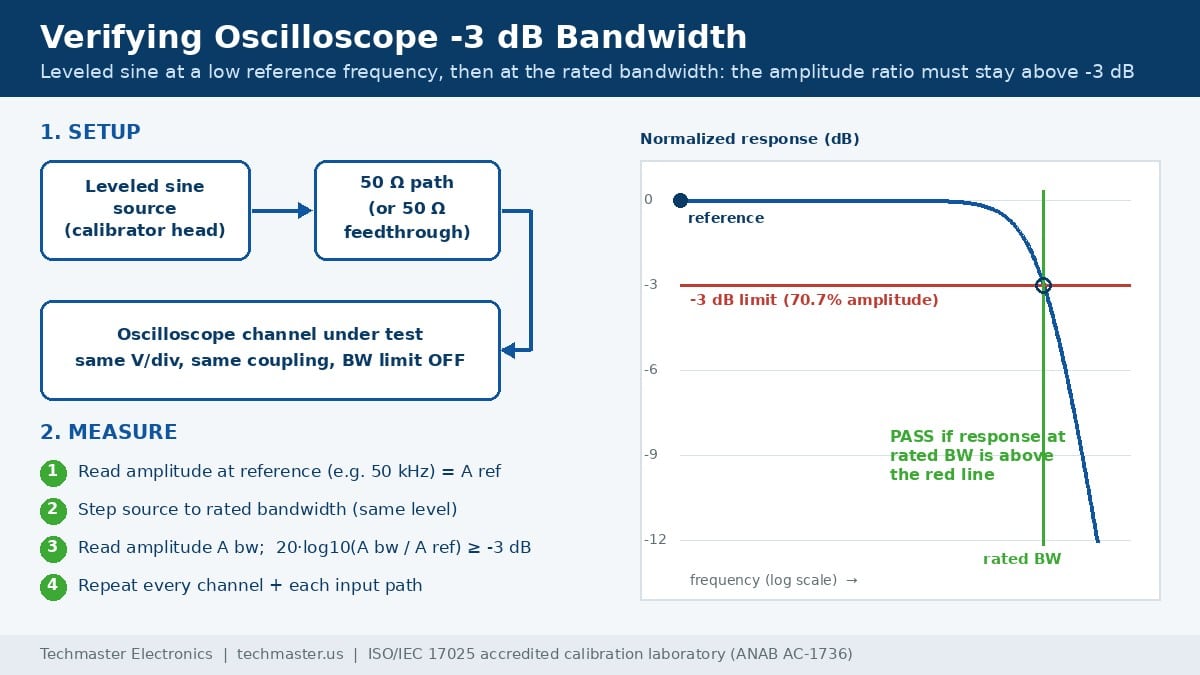
The vertical system of an oscilloscope behaves like a low-pass filter. At low frequencies it passes the signal unchanged. As frequency rises, the response rolls off, and the specified bandwidth is the frequency at which the displayed amplitude has fallen to 70.7% of its low-frequency value. That is the -3 dB point.
Engineers rarely measure a pure sine at the bandwidth limit. They look at clock edges, serial data, switching transients and pulse widths. Those signals contain harmonics well above their fundamental frequency, and a degraded front end rounds the edges, lowers the amplitude of narrow pulses, and hides overshoot or ringing that is actually present on the board. The error looks like a real circuit behavior, which is what makes it dangerous.
That is why manufacturers such as Keysight, Tektronix, Rohde & Schwarz and Teledyne LeCroy include a bandwidth check in their performance verification procedures, and why oscilloscope calibration bandwidth checks should never be dropped in favor of a DC-only check. Techmaster’s internal ten-year record of 381,916 calibrations includes more than 2,700 oscilloscope calibrations in the electrical discipline, and front-end response is one of the parameters most worth checking on every one of them.
How is -3 dB bandwidth verified during calibration?
The source is usually an oscilloscope calibrator with a leveled sine function, such as a Fluke 5522A fitted with an SC600 or SC1100 option, or a Fluke 9500B with active heads that deliver the signal right at the scope input. The word leveled matters: the source holds its output amplitude flat across frequency, so any change on the screen is the scope’s response, not the source’s.
For bandwidths beyond the calibrator’s range, labs often use an RF signal generator, a power splitter and a power meter. One splitter arm feeds the oscilloscope and the other feeds a power sensor, so the lab knows the actual level arriving at the scope input at each frequency. Either way, the test follows the manufacturer’s service procedure, which sets the reference frequency, the vertical scale and the pass limit.
Settings that change the result
A few setup details decide whether the number is meaningful. The bandwidth-limit filter must be off for the full-bandwidth test, and checked separately when it is part of the specification (a 20 MHz limit should itself land near its -3 dB point). Input termination must match the specification being tested: many oscilloscopes specify a lower bandwidth on the 1 MΩ path than on the 50 Ω path, and the two front ends are different circuits. Vertical scale matters too, because some instruments specify reduced bandwidth on their most sensitive ranges.
If you also use passive or active probes, remember that the system bandwidth is the scope and probe together. Probe checks are covered in our guide to oscilloscope probe calibration, compensation and bandwidth.
How are bandwidth and rise time related?
The relationship comes from the shape of the frequency response. A slower, gentler roll-off produces a cleaner step response with little overshoot. A flatter response that drops sharply near the bandwidth limit gives a faster edge for the same -3 dB frequency, but with more pre-shoot and ringing. That is why manufacturers quote different constants for different product families, and why you should read the specific data sheet instead of assuming 0.35.
The table below shows the expected rise time at both ends of that range, and the source edge speed needed to measure each one with about 2% error or less.
| Oscilloscope bandwidth | Rise time at 0.35/BW | Rise time at 0.45/BW | Source edge for ≤2% error (5× faster) |
|---|---|---|---|
| 100 MHz | 3.5 ns | 4.5 ns | ≤ 700 ps |
| 200 MHz | 1.75 ns | 2.25 ns | ≤ 350 ps |
| 500 MHz | 700 ps | 900 ps | ≤ 140 ps |
| 1 GHz | 350 ps | 450 ps | ≤ 70 ps |
| 2 GHz | 175 ps | 225 ps | ≤ 35 ps |
| 4 GHz | 87.5 ps | 112.5 ps | ≤ 17.5 ps |
The last column uses the conservative 0.35 value. It shows why rise-time verification becomes difficult quickly: above about 1 GHz, the source edge must be in the tens of picoseconds, which only specialized pulse heads and pulse generators provide.
How fast must the calibration edge be?
Rise times in a measurement chain combine approximately as a root sum of squares, a simplification that holds well for Gaussian-like responses. If the oscilloscope’s true rise time is 350 ps and the calibrator edge is 150 ps, the screen shows about 381 ps. Without a correction, the reading is about 9% slow, enough to fail a scope that is actually in specification.
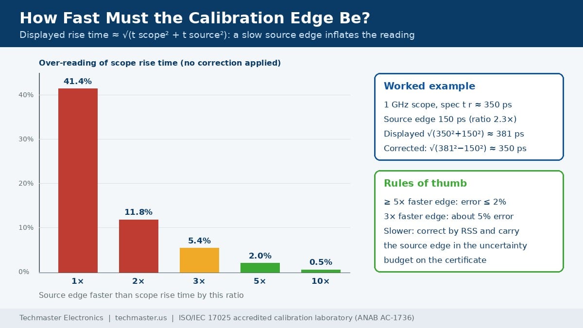
There are two legitimate ways to handle a source that is not fast enough. The lab can correct the reading by subtracting the source contribution in quadrature, or it can widen the acceptance limit. In both cases the source’s own rise time, and its uncertainty, belong in the uncertainty budget, evaluated under the JCGM 100 Guide to the Expression of Uncertainty in Measurement (GUM). A certificate that reports a corrected rise time without saying so is a red flag.
Is rise time actually measured or only calculated?
Manufacturers separate warranted specifications, which are tested, from typical or characteristic values, which describe design performance but are not verified on every unit. Rise time frequently falls into the second group. A calibration that follows the service manual will then report bandwidth, and the certificate may never mention rise time at all.
That is not a lab error; it is a scope-definition decision. If your application is pulse timing, edge-rate compliance or signal-integrity work, ask for a fast-edge step test as an added point. The same test also shows overshoot, pre-shoot and settling, which a sine sweep cannot reveal. Our step-by-step guide to ISO/IEC 17025 oscilloscope calibration lists the other parameters a full calibration covers.
What should the calibration certificate show?
Under ISO/IEC 17025:2017 (clauses 7.1.3 and 7.8.6), when a customer requests a statement of conformity, the decision rule must be agreed with the customer, and the report must identify the rule applied unless it is inherent in the specification. The ILAC G8 guidance on decision rules and statements of conformity explains how measurement uncertainty is taken into account when a result sits close to the limit. A bandwidth reading of -2.9 dB against a -3 dB limit, with 0.3 dB of uncertainty, is not a clean pass under every rule.
| Certificate item | What good looks like | Red flag |
|---|---|---|
| Channels and paths | Every channel, 50 Ω and 1 MΩ where specified | Only channel 1, or only one input path |
| Frequencies | Reference and rated bandwidth stated | “Bandwidth: Pass” with no frequency |
| Measured value | Response in dB or percent of reference | No data, only a checkbox |
| Uncertainty | Expanded uncertainty (k=2) per point | No uncertainty on an accredited report |
| Decision rule | Named rule, e.g. guard band or simple acceptance | No rule stated |
| Rise time (if tested) | Source edge stated, correction declared | Rise time listed with no source information |
| As-found and as-left | Both recorded if any adjustment was made | Only as-left data after a repair |
For a deeper look at reading pass and fail near a limit, see our explanation of test uncertainty ratio and decision rules on calibration certificates, and why as-found versus as-left calibration data matters for impact assessments.
What causes bandwidth and rise-time failures?
The 50 Ω input is the most fragile part of a high-bandwidth scope. Many are rated for only a few volts RMS, and connecting a 1 MΩ-type signal by mistake can damage the termination or the front end. Damaged connectors cause impedance mismatch, which shows up as ripple in the frequency response and ringing on edges.
A self-calibration routine corrects internal gain and offset, but it cannot restore bandwidth lost in a damaged amplifier. If an oscilloscope fails bandwidth, the next step is usually repair of the front end or channel board, followed by a full recalibration. Typical findings and their checks are summarized below.
- Bandwidth low on one channel only: suspect that channel’s input connector, termination or front-end amplifier.
- Bandwidth low on all channels: check setup first: bandwidth limit, termination, probe, cable and adapters.
- Ripple across frequency: look for connector damage or impedance mismatch in the test path.
- Excess overshoot on the step response: possible front-end peaking or mismatch; confirm with a known-good fast edge.
How often to check depends on use and risk; our guide on how often to calibrate an oscilloscope covers interval setting.
Key Takeaways
- Bandwidth is the frequency where displayed amplitude falls to 70.7% (-3 dB); it is verified with a leveled sine at a reference frequency and at rated bandwidth.
- Rise time is roughly 0.35 to 0.45 divided by bandwidth, depending on the scope’s roll-off shape.
- A rise-time test needs a source edge three to five times faster than the scope, or a declared root-sum-of-squares correction.
- Rise time is often a calculated, not tested, specification; request a measured point if your work depends on edges.
- Check that the certificate covers every channel and input path, with uncertainty and a stated decision rule.
- Techmaster’s calibration services are performed in four labs accredited by ANAB under certificate AC-1736; see our accreditation details.
FAQ
Is oscilloscope rise time measured during a standard calibration?
Not always. Many manufacturers publish rise time as a calculated or typical value derived from bandwidth, and their service procedures verify only the -3 dB bandwidth. If your application depends on edge timing, ask the lab in writing to measure rise time with a fast-edge source and report the value and its uncertainty.
What reference frequency is used for an oscilloscope bandwidth test?
The manufacturer’s procedure sets it. A low reference such as 50 kHz or 1 MHz is common. The leveled sine amplitude is read at the reference, then at the rated bandwidth at the same source level, and the ratio must not fall below -3 dB, which is 70.7% of the reference amplitude.
Why does my 1 GHz oscilloscope show a slower rise time than its specification?
Every element in the path adds rise time. The displayed value is roughly the root sum of squares of the scope, probe and source rise times. A 150 ps source on a 350 ps scope reads about 381 ps. Probes, adapters, long cables and a bandwidth-limit filter left on also slow the displayed edge.
Do I need the 1 MΩ input path calibrated separately from the 50 Ω path?
Yes, if you use it. Many oscilloscopes specify a lower bandwidth on the 1 MΩ input than on the 50 Ω input, and the two paths use different front-end circuits. A certificate that lists only 50 Ω bandwidth results does not prove the 1 MΩ path performs to its own specification.
How fast must the calibration edge be to verify rise time?
Aim for a source edge at least three to five times faster than the oscilloscope’s rise time. At five times faster the uncorrected over-reading is about 2%; at three times it is about 5%. Slower edges can still be used if the lab corrects by root sum of squares and includes the source edge in the uncertainty budget.
Can Techmaster verify oscilloscope bandwidth under ISO/IEC 17025 accreditation?
Techmaster Electronics calibrates oscilloscopes in its ISO/IEC 17025 accredited laboratories in Vista and Santa Clara, California, Orlando, Florida, and San Antonio, Texas, under ANAB certificate AC-1736. Whether a specific bandwidth or rise-time point is covered depends on the published scope of accreditation, so confirm the range when you request a quote.
Need oscilloscope bandwidth verified with data you can defend in an audit?
Techmaster Electronics has calibrated test equipment since 1989 in ISO/IEC 17025 accredited laboratories in Vista and Santa Clara, California, Orlando, Florida, and San Antonio, Texas (ANAB AC-1736).
Request an oscilloscope calibration quote
Khanh Nguyen is the Marketing Manager at Techmaster Electronics, a B2B marketing leader covering the test, measurement, and ISO/IEC 17025 accredited calibration industry in the United States.