
TL;DR: Noise figure analyzer calibration verifies the whole measurement chain, not just a box: noise figure and gain against known standards, the excess noise ratio of the source, level and frequency response accuracy, input match and the loss corrections ahead of the device under test. Noise figure is a difference of small numbers, so every error in that chain lands on the result at full size.
What is noise figure analyzer calibration?
Noise figure analyzer calibration is the traceable verification of the instrument and the noise source that together measure how much noise a device adds to a signal, the measurement that decides whether a low-noise amplifier, receiver or front end meets specification. The analyser and the source are calibrated as a pair, because the source’s excess noise ratio is the reference the measurement is built on.
RF and microwave instruments were one of the larger clusters in the requests reaching our laboratories over the last quarter, and noise measurement equipment appeared in several of them alongside power sensors, counters and signal analysers, usually with accredited calibration and as-found data specified explicitly.
Why is the whole chain the instrument?
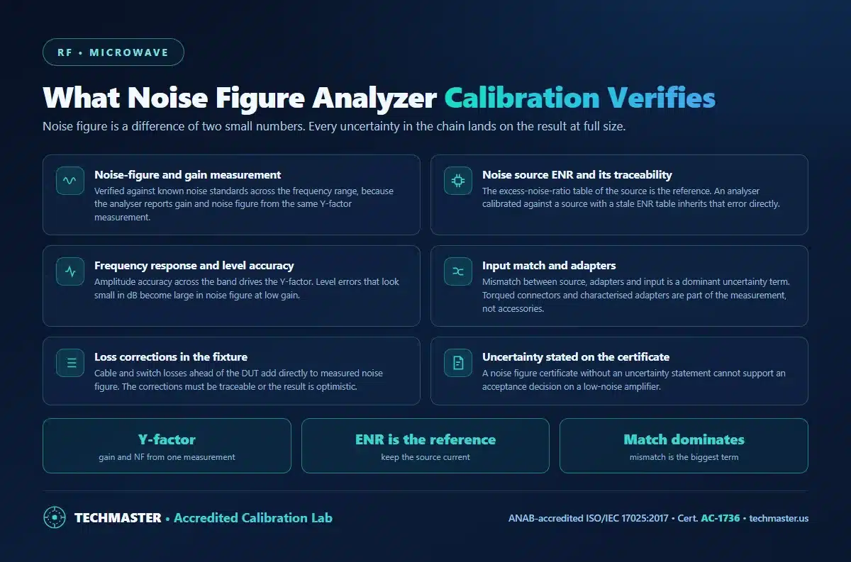
Because noise figure is computed from a Y-factor: the ratio of noise power measured with the source hot and cold. Any error in the source’s excess noise ratio, in the analyser’s amplitude accuracy, in the match between source, adapters and input, or in the loss correction for cables and switches ahead of the device under test appears in the result directly, and low-gain devices magnify all of it.
This is why the noise source is treated as the primary reference. The behaviour and drift of that source is the subject of noise source ENR calibration, and it is the single item most often overlooked when a noise figure result stops making sense.
Which uncertainty terms dominate?
| Contributor | Why it matters | How it is controlled |
|---|---|---|
| Noise source ENR table | It is the reference for the whole measurement | Current traceable calibration; keep the table with the source |
| Mismatch at the DUT input | Source impedance changes between hot and cold states | Characterised adapters, torqued connectors, isolators where needed |
| Analyser level accuracy | Errors in dB become larger errors in noise figure | Verified amplitude accuracy across the band |
| Fixture and cable loss | Loss ahead of the DUT adds directly to noise figure | Traceable loss corrections, measured not assumed |
| Low device gain | Second-stage noise contributes more as gain falls | Second-stage correction, verified analyser noise figure |
| Ambient temperature assumption | The cold state is assumed to be at a stated temperature | Recorded lab temperature and a stated assumption |
Connector care is not a detail at these frequencies, the same discipline that keeps a VNA usable applies here, as set out in VNA calibration kit verification. Amplitude accuracy on the analyser side sits alongside the work described in spectrum analyzer calibration and network analyzer calibration.
What is accredited, and where?
Noise figure measurement to 26.5 GHz is on Techmaster’s ANAB ISO/IEC 17025 scope (Cert. AC-1736), with power sensor calibration factors and single-sideband phase noise to 50 GHz, at the Vista, Santa Clara and Orlando laboratories. RF and microwave work is not performed at the San Antonio laboratory.
Power measurement is the closest neighbour to this work, because the same sensors and the same connector discipline are involved, see power sensor calibration accuracy and average power sensor calibration. For aerospace and defence supply chains where the flow-downs are explicit, RF and microwave calibration for AS9100 suppliers covers the documentation expected.
What should the certificate say?
It should state the measurement uncertainty, not just a pass. A noise figure result quoted without an uncertainty cannot support an acceptance decision on a low-noise amplifier, because the specification margin is often smaller than the measurement uncertainty itself. How that budget is constructed is explained in how to build a measurement uncertainty budget.
Frequently asked questions
What does noise figure analyzer calibration verify?
Noise figure and gain measurement against known noise standards across the frequency range, amplitude and frequency response accuracy, input match behaviour, and the corrections applied for losses ahead of the device under test. Because noise figure is derived from a Y-factor ratio, an error in level accuracy or match propagates straight into the reported figure.
Does the noise source need calibrating as well as the analyzer?
Yes, and it is the more important of the two. The excess noise ratio table of the noise source is the reference the whole measurement is built on, so an analyser calibrated against a source with a stale or drifting ENR table inherits that error directly. Calibrate the source and the analyser as a pair, and keep the ENR table with the instrument.
Why is mismatch such a large uncertainty in noise figure measurement?
Because the source impedance presented to the device under test changes between the hot and cold states of the noise source, and any reflection between the source, adapters and analyser input alters the noise power actually delivered. Mismatch is frequently the dominant uncertainty term, which is why characterised adapters and correctly torqued connectors are part of the measurement rather than accessories.
Is noise figure measurement on Techmaster’s accredited scope?
Yes, within a defined range. RF and microwave capability on the ANAB ISO/IEC 17025 scope (Cert. AC-1736) includes noise figure to 26.5 GHz, with power sensor calibration factors and single-sideband phase noise to 50 GHz, at the Vista, Santa Clara and Orlando laboratories. RF and microwave work is not performed at the San Antonio laboratory, so send the model list and the frequencies involved and the right lab is chosen for you.
The bottom line
Calibrate the source with the analyser, control the match, correct the losses ahead of the device, and read the uncertainty on the certificate. Noise figure punishes shortcuts more than almost any other RF measurement.
Need a quote, a rental, or a repair evaluation?
Techmaster Electronics, ISO/IEC 17025 accredited calibration laboratory, ANAB Cert. AC-1736, founded 1989. Five US labs, 5-day standard turnaround, 1–2 day expedite.
Request a quote →Techmaster Electronics, LLC is an independent ISO/IEC 17025:2017 accredited calibration laboratory. We are not affiliated with, authorized by, or endorsed by any manufacturer named on this page. All product names and model designations are trademarks of their respective owners and are used here only to identify the equipment we calibrate, repair, or rent. Confirm that our accredited scope covers your instrument’s parameters and ranges before shipping, ask us and we will check it against your model list.

Khanh Nguyen is the Marketing Manager at Techmaster Electronics, a B2B marketing leader covering the test, measurement, and ISO/IEC 17025 accredited calibration industry in the United States.