
Soldering Iron Tester Calibration
Why calibration intervals matter
How Soldering Iron Tester calibration works
- Intake & visual inspection
- Environmental stabilization
- As-found measurement
- Comparison to NIST-traceable standards
- Adjustment if required
- As-left results & certificate
Your calibration, covered
In-lab vs on-site calibration
In-lab calibration
- Accredited bench with full reference standards
- Best achievable measurement uncertainties
- Pickup & return logistics handled
- Ideal for precision and reference work
On-site calibration
- We calibrate the Soldering Iron Tester at your facility
- No shipping risk or transit downtime
- As-found data captured before any move
- Ideal for fixed, large or sensitive assets
In-depth guide
Soldering Iron Tester Calibration: Ensuring Precision Thermal Validation
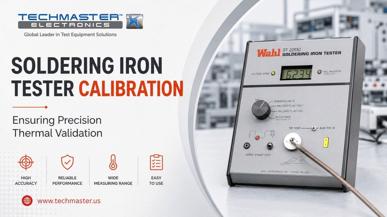
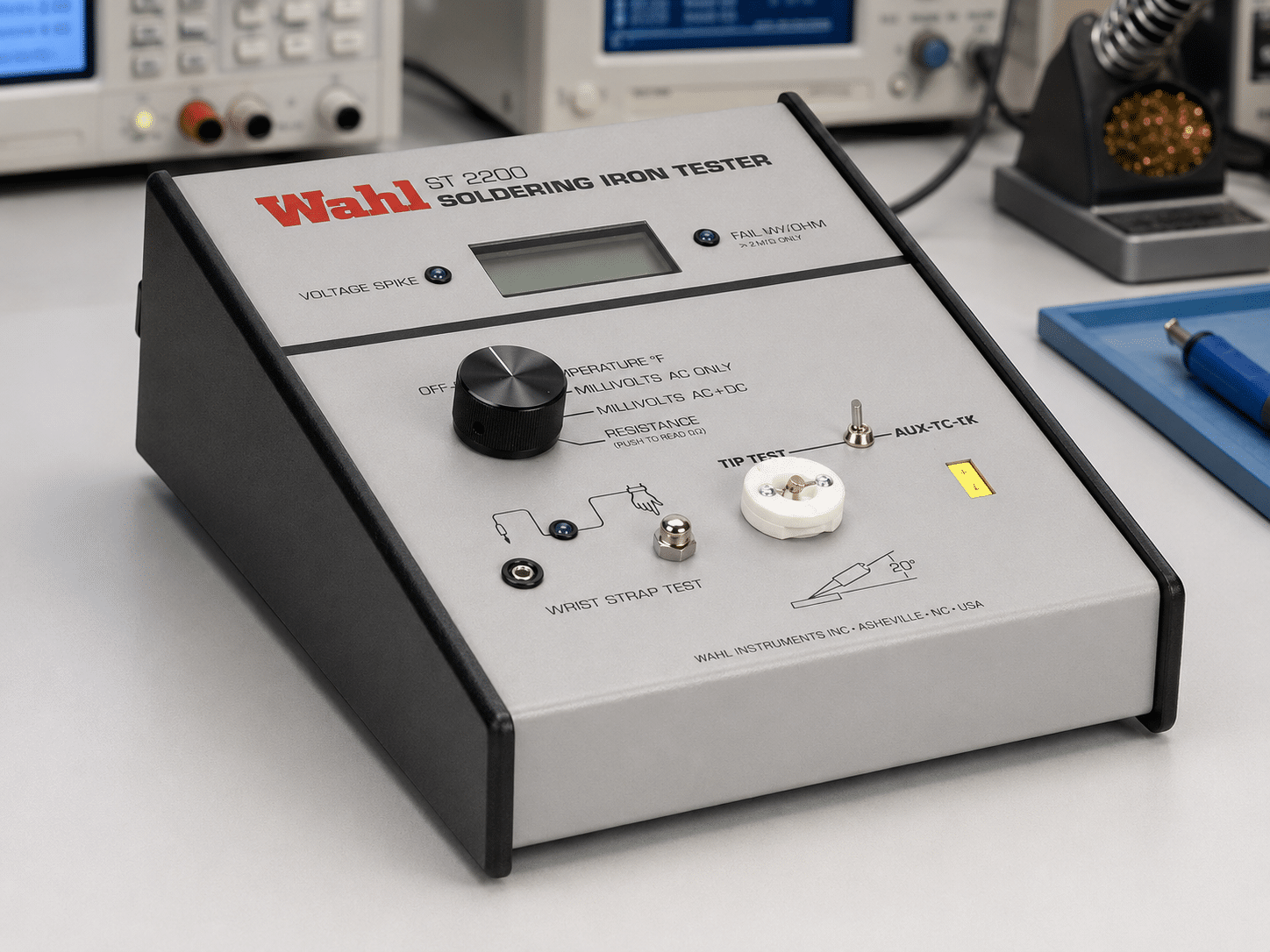
In the high-stakes world of precision electronics manufacturing, high-density printed circuit board (PCB) assembly, and delicate rework, controlling the temperature at the soldering iron tip is critical to structural integrity. Quality control engineers and production technicians rely on specialized instruments, such as the Wahl ST2200 Soldering Iron Tester, to validate that tip temperatures remain strictly within engineering specifications. This instrument measures the heat transfer from the tip to a sensor, providing the digital data necessary to calibrate and verify soldering stations across the production floor.
However, due to harsh operating environments, extreme heat, and constant exposure to chemical fluxes, the accuracy of these testers inevitably degrades over time. Thermocouple sensors experience surface wear, internal processing amplifiers drift, and thermal residue accumulates, causing hidden measurement errors. When a production line operates with an unverified tester, boards may suffer from “cold” solder joints—resulting in intermittent electrical contact—or “thermal shock,” which damages expensive semiconductor components. Therefore, routine, accredited soldering iron tester calibration is the only reliable way to maintain national traceability, protect sensitive electronics, and guarantee total manufacturing quality.
1. Technical Principles: Thermocouple Sensors and Heat Transfer Mechanics
1.1. What are the fundamental engineering factors affecting soldering iron tester accuracy?
Soldering Iron Tester Calibration is the specialized metrological evaluation of a thermal measurement instrument against traceable heat reference standards. This process assesses the linearity of the thermocouple sensor, verification of heat transfer impedance, and the correction of internal thermoelectric voltage drift.
1.2. Sensor Drift and Heat Transfer Errors
Soldering iron testers typically utilize K-type thermocouples to receive thermal energy. Over time, the internal metal junctions of the sensor experience chemical and structural changes due to constant exposure to high temperatures, leading to sensitivity drift. Furthermore, the oxidation of the sensor’s contact surface creates an insulating barrier that hinders efficient heat transfer from the soldering tip, causing the tester to display temperatures significantly lower than the actual tip temperature.
To address this, the calibration process requires verifying the stability and responsiveness of the sensor surface. Metrologists use reference heat sources with stable thermal conductivity to verify the sensor’s ability to accurately register heat flux. If the sensor can no longer transfer heat efficiently, calibration helps determine exactly when the sensor must be replaced to maintain measurement integrity.
1.3. Cold-Junction Compensation (CJC) Accuracy
Digital temperature testers operate based on the temperature difference between the probe tip and the “cold junction” (where the sensor connects to the meter’s internal circuitry). Aging of the semiconductor components responsible for compensating for ambient temperature at the cold junction causes significant cumulative errors. This effect is especially pronounced in factory environments where ambient temperatures fluctuate. Professional calibration utilizes controlled thermal chambers to verify this compensation function, ensuring the device remains accurate across varying working environments.
2. Industrial Applications: Where Thermal Control Protects Quality
How does precise soldering temperature verification impact manufacturing workflows?
Validating the accuracy of thermal testers provides production teams with a reliable benchmark to control the soldering process. This verification prevents dangerous soldering errors, ensuring robust connections and meeting strict manufacturing quality standards.
-
Electronic PCBA Manufacturing: When assembling ultra-miniature Surface Mount Devices (SMD), precise thermal profiles are mandatory. If a tester displays incorrect data, the operator might use a soldering iron that is too hot (causing internal component damage) or too cold (resulting in weak, intermittent solder joints).
-
Medical Device Repair: High-reliability medical equipment demands absolute precision. Manual soldering with temperature-validated irons ensures that connections meet durability and conductivity standards, preventing critical system failures in life-saving equipment.
-
Telecommunications Infrastructure: Solder joints in telecom hardware must withstand harsh outdoor temperature cycling. Using irons verified by calibrated testers ensures uniform joint formation, which significantly extends the operational lifespan of the hardware.
3. The Calibration Pillar: Securing Traceability and ISO/IEC 17025 Compliance
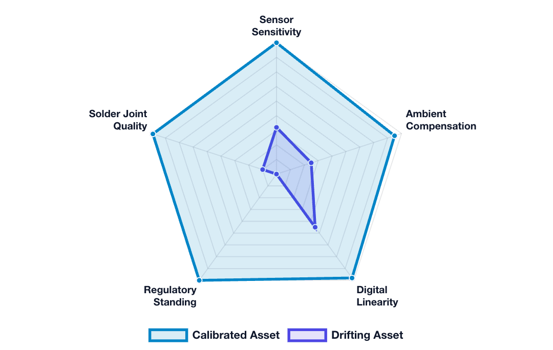
Performance Breakdown
A comparison between calibrated instruments and drifting sensors. Drift compromises linearity and ambient corrections, risking failed quality management system (QMS) audits.
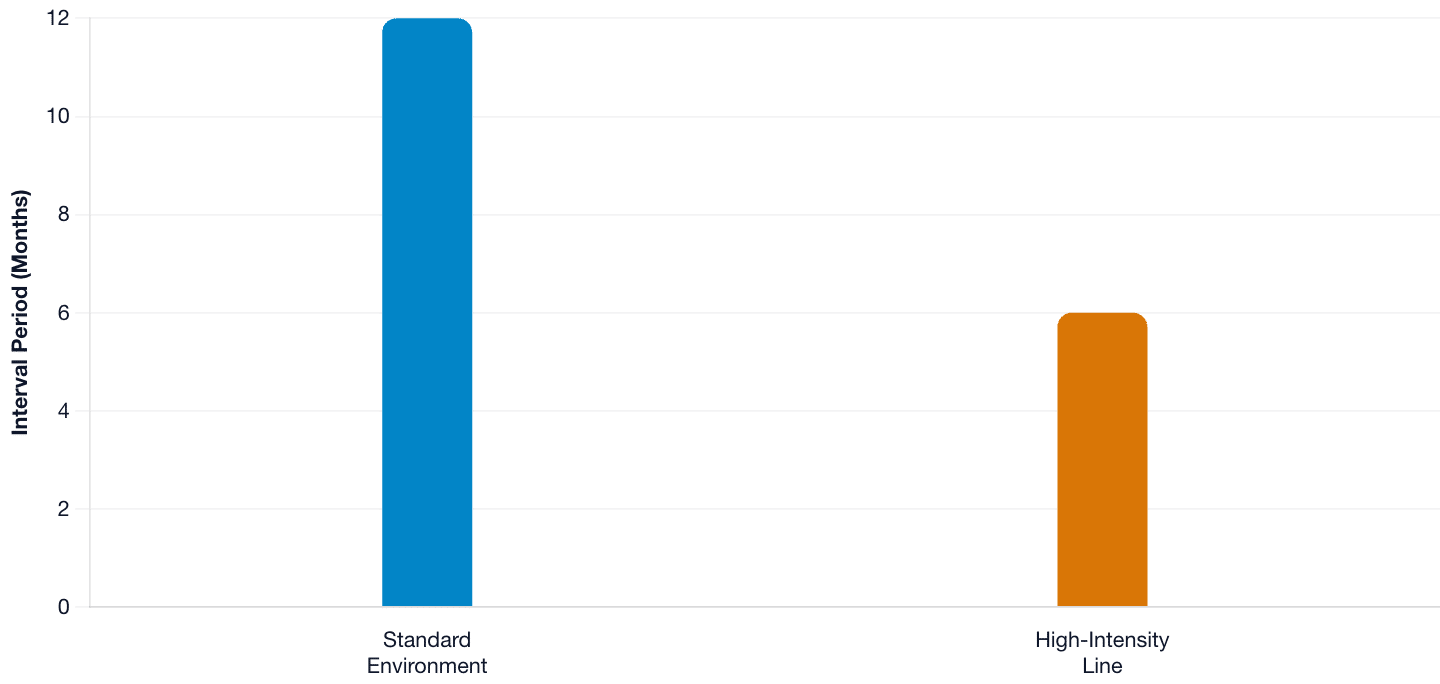
Calibration Frequency Standards
Regular intervals ensure total operational confidence. Standard operations suggest a 12-month sequence, while aggressive manufacturing floors demand a 6-month cycle to combat severe sensor erosion.
Why is traceable metrological testing mandatory for thermal measurement assets?
Accredited soldering iron tester calibration connects shop-floor thermal metrics directly to international standards through an unbroken chain of precision laboratory comparisons. This rigorous oversight determines measurement uncertainty, fulfills quality benchmarks, and defends production facilities against liability claims.
Operating unverified thermal measurement instruments introduces massive compliance and quality risks into a manufacturing workflow. Because sensor drift occurs slowly without showing clear mechanical symptoms, testers often provide data that seems plausible but is entirely incorrect. If a quality control team uses a drifted tester to validate their assembly stations, entire batches of products may fail field reliability tests, leading to costly recalls and audit failures.
Implementing an ISO/IEC 17025 accredited calibration schedule thoroughly mitigates these operational risks. Certified metrologists verify thermal measurement instruments using reference heat sources that maintain direct traceability to the National Institute of Standards and Technology (NIST). This empirical process calculates exact device uncertainties and issues an official calibration certificate. This formal document satisfies external quality auditors, confirms engineering parameters, and validates your manufacturing integrity.
4. How to Prepare a Soldering Iron Tester for Calibration
Following this precise checklist ensures your thermal measurement instruments are structurally optimized for an upcoming field or laboratory calibration session.
1. Inspect the Sensor Surface and Protective Housing
Carefully check the sensor tip for deformation, corrosion from soldering flux, or physical damage. The surface must be clean and free from old solder residue. If the sensor is heavily oxidized or coated with debris, calibration accuracy will be severely compromised.
2. Verify Cables and Power Supplies
Ensure that the signal cable connecting the probe to the display unit is free from nicks or frayed insulation. Check the status of internal batteries or DC power adapters to ensure stable operation during the measurement verification process.
3. Implement Ambient Thermal Stabilization
Place the tester inside the laboratory environment for at least four hours before starting measurements. This “soaking” period allows internal electronic components to reach thermal equilibrium with the environment, neutralizing warm-up drift.
4. Document Configuration and Baseline State
Provide the calibration laboratory with the device’s exact serial number, firmware version, and a description of any known anomalies (e.g., “displays lower temperatures than expected”). This information helps metrologists focus their diagnostics on the root cause of the instrument’s performance drift.
Techmaster US: Your Partner for Certified Instrument Calibration
Why Choose Techmaster US for Certified Equipment Calibration?
-
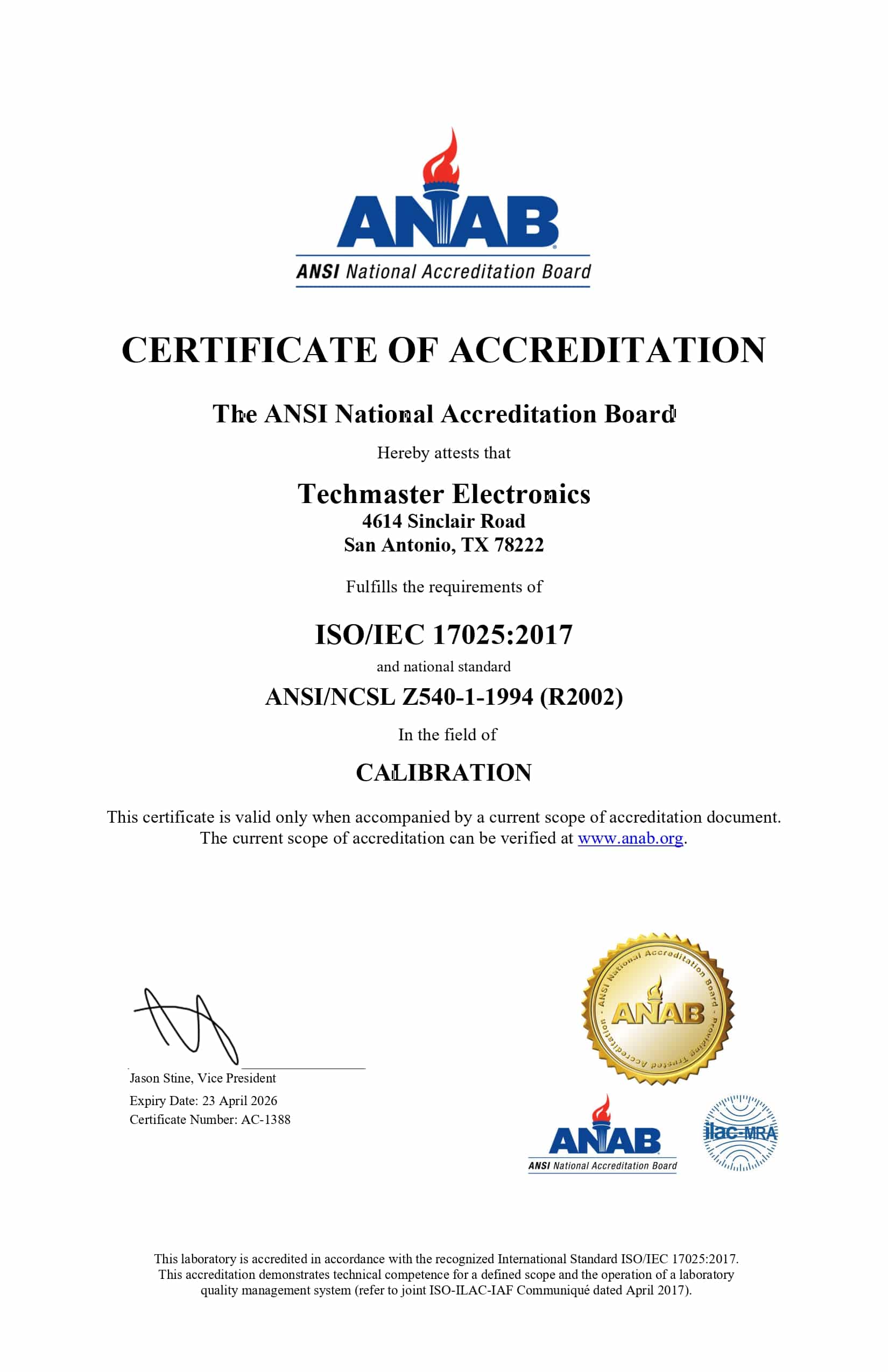
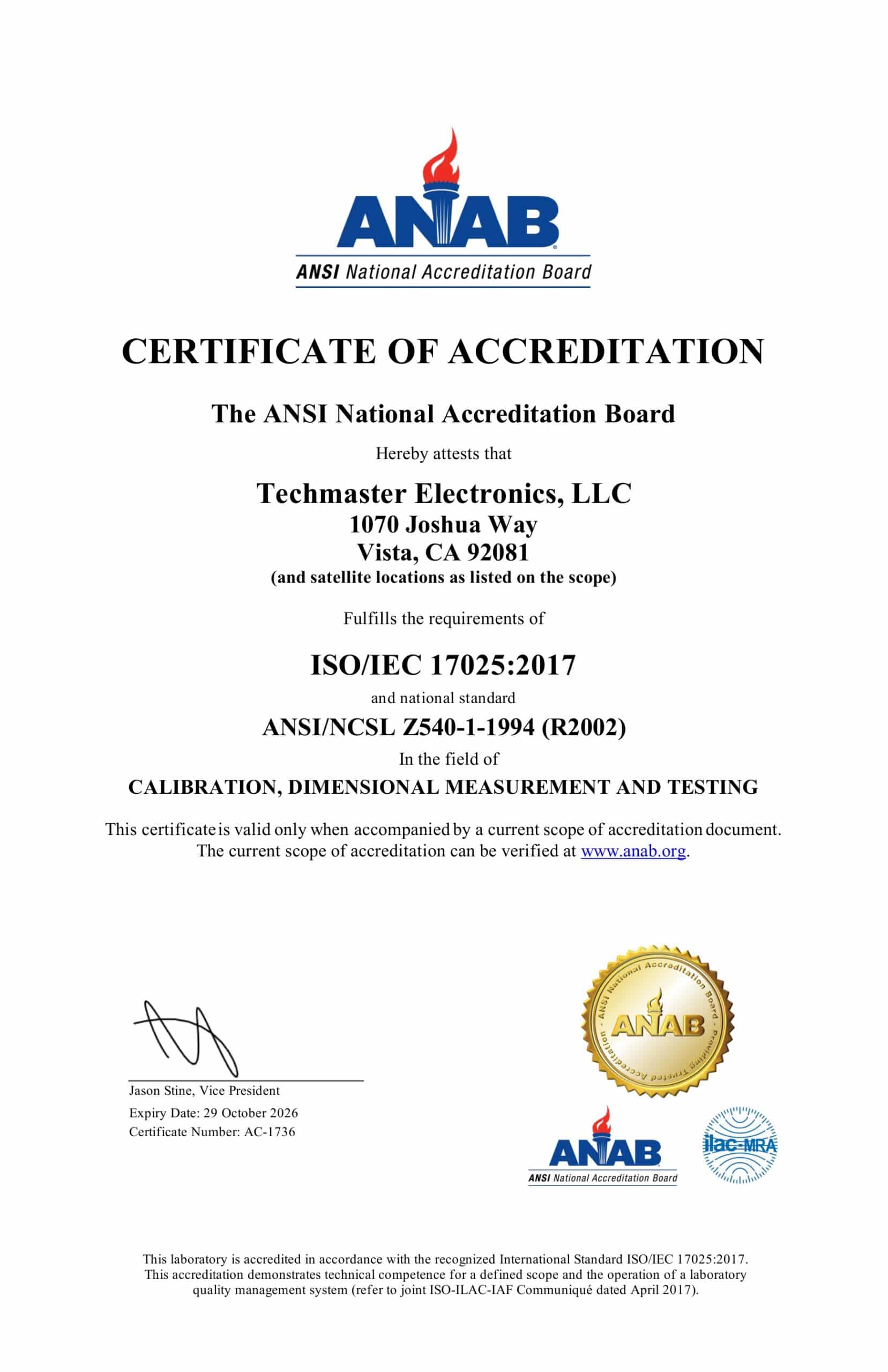
Full ISO/IEC 17025 Accreditation: Every technical procedure is executed under the strict quality governance of our ANAB cert AC-1736 framework.
-
Rapid On-Site Field Calibration: We deploy fully equipped mobile laboratories to verify your test systems directly at your production plant, minimizing asset downtime.
-
Comprehensive Metrological Scope: Our capabilities span advanced electronics, thermodynamics, dimensional parameters, and mechanical systems across your entire industrial footprint.
Do not allow sensor oxidation or thermal drift to compromise your solder joint quality or jeopardize your compliance standing. Contact Techmaster US today to receive an expert technical quote tailored to your facility’s unique instrument requirements.
Frequently Asked Questions (FAQs)
1. What is the recommended frequency for soldering iron tester calibration?
Soldering Iron Tester Calibration should be performed every twelve months to ensure absolute accuracy. However, if the device is used daily in high-intensity production environments, a six-month calibration interval is highly recommended to protect solder joint quality.
2. Can I calibrate a thermal tester using a standard thermometer?
No. Standard thermometers lack the resolution, thermal mass compensation, and heat-transfer verification capabilities required for soldering tip validation. Proper calibration requires specialized thermal calibrators in an accredited laboratory environment to ensure precision and traceability.
3. Why do sensor probes wear out so quickly?
Sensor probes are subjected to extreme temperatures (often >300°C) and corrosive chemicals from solder flux. This exposure causes oxidation and alters the material structure of the thermocouple, leading to reduced sensitivity and measurement errors.
4. What are the benefits of ISO/IEC 17025 certification for electronics manufacturing?
This certification provides legally defensible proof that your test equipment was verified using audited procedures and traceable reference standards. It is a mandatory requirement for clearing international quality audits from major clients and industry regulators.
5. What are the signs that my soldering iron tester requires recalibration?
If you notice that the temperature readings fluctuate inconsistently for the same soldering station, or if solder joints appear consistently defective (too dry or burned) despite using standard settings, it is a clear indicator that your tester requires immediate recalibration.
Ready to secure your compliance?
Contact Techmaster US’s ANAB-accredited experts today.
Frequently asked questions
What is Soldering Iron Tester Calibration?
How often should a Soldering Iron Tester be calibrated?
What standards apply to Soldering Iron Tester Calibration?
What is included on the certificate?
Can you calibrate the Soldering Iron Tester on-site?
Need Soldering Iron Tester calibration?
ANAB-accredited, NIST-traceable, fast turnaround — in-lab or on-site across the USA.
Contact us for a quoteReferences & industry standards
- ISO/IEC 17025 testing & calibration laboratory requirements
- NIST calibration services and measurement traceability
- A2LA / ANAB accreditation for calibration laboratories
External standards bodies. Techmaster Electronics is an ISO/IEC 17025-accredited, NIST-traceable calibration laboratory.

Calibration engineer at Techmaster Electronics, ISO/IEC 17025 accredited laboratory with 35+ years of metrology expertise.
