

How to Use an Ultrasonic Flaw Detector: Setup, Operation & Best Practices
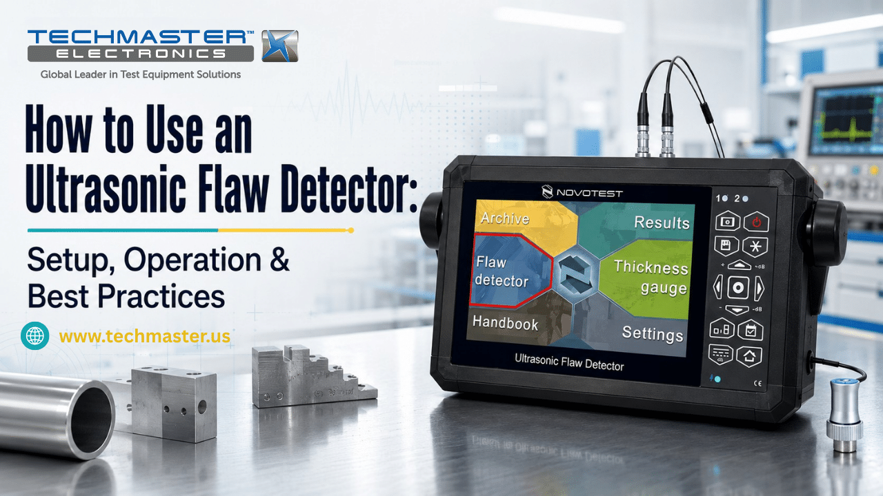
For Non-Destructive Testing (NDT) technicians, QA managers, and field inspection engineers, knowing how to use an ultrasonic flaw detector is essential for accurate inspection. The instrument helps detect internal cracks, voids, and other flaws without damaging the test material. However, incorrect probe setup or poor calibration can lead to wrong results. Therefore, technicians should follow a clear setup process before every inspection. Proper probe selection, sound velocity calibration, gain adjustment, and scanning technique all help improve test accuracy. In addition, regular professional calibration keeps the instrument within its required performance limits.
Ultrasonic flaw detector calibration is not on Techmaster’s ANAB ISO/IEC 17025 scope (certificate AC-1736). We calibrate ultrasonic flaw detectors with NIST-traceable reference standards and issue a NIST-traceable certificate. See what is on our accredited scope.
1. How to Set Up and Operate an Ultrasonic Flaw Detector
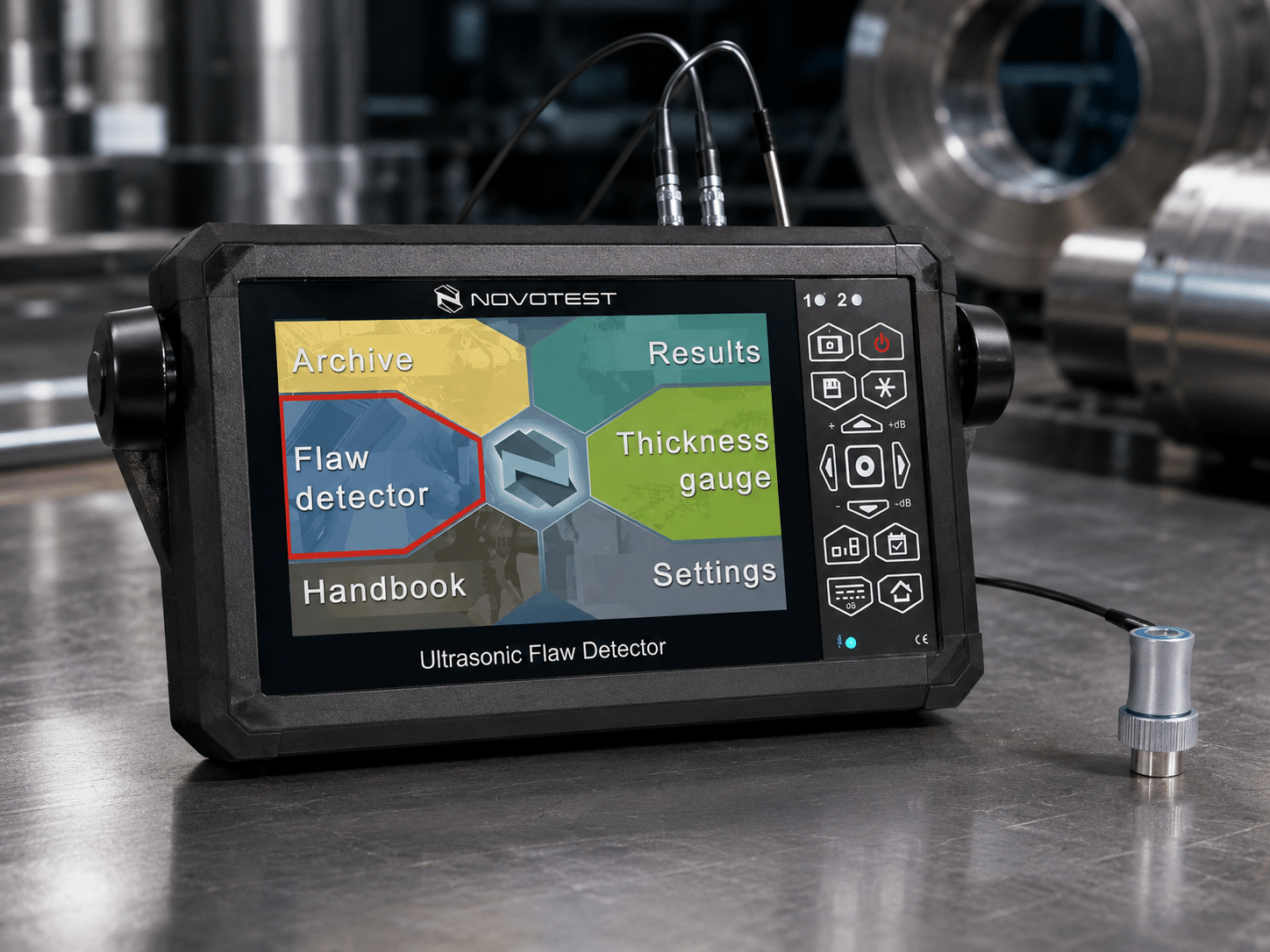
Before starting an inspection, technicians should prepare the instrument and test material carefully. The following steps provide a practical setup process.
1.1. Allow the Instrument to Warm Up
First, turn on the ultrasonic flaw detector and allow it to warm up for about 15 to 30 minutes. This period gives the internal timing circuits and electronic components time to reach a stable operating condition. As a result, the instrument can provide more stable readings during the inspection.
1.2. Select and Connect the Correct Probe
Next, choose a probe that matches the inspection task. Common options include straight-beam and angle-beam transducers.
For example, straight-beam probes work well for detecting flaws below relatively flat surfaces. In contrast, angle-beam probes are often useful for weld inspection and angled defect detection.
Before testing, inspect the probe face and cable. Make sure the connector is clean and secure. A damaged cable or worn probe can add noise and reduce signal quality.
1.3. Calibrate Sound Velocity and Zero Offset
After connecting the probe, place it on a certified calibration block. Apply a suitable acoustic couplant between the probe and the block.
Then, adjust the sound velocity and zero-delay settings. Use two known thickness points on the reference block to confirm the correct time-base response.
This step is important because sound velocity changes between different materials. Therefore, using the wrong velocity can result in an incorrect flaw depth.
1.4. Set the Gain and DAC or TCG Curve
Next, adjust the receiver gain to obtain a clear and stable reference signal. For many applications, technicians use a calibration block with known reflectors.
Depending on the inspection method, you may also create a Distance Amplitude Correction (DAC) or Time Corrected Gain (TCG) curve.
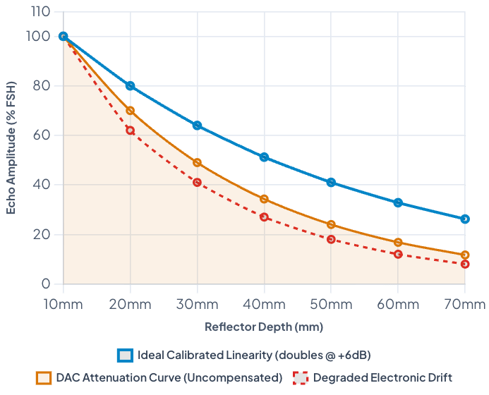
These functions help compensate for signal loss as sound travels deeper into the material. Therefore, technicians can compare reflector signals more consistently at different depths.
1.5. Apply Couplant and Start Scanning
Before scanning, apply enough acoustic couplant to create good contact between the probe and the test surface.
Then, move the probe across the test area at a steady speed. Maintain consistent pressure and keep the probe properly aligned.
At the same time, watch the A-scan display for unusual echoes. If an echo exceeds the selected evaluation level, stop and examine the area more closely.
Finally, record the inspection results according to your test procedure and quality requirements.
2. Best Practices for Accurate Ultrasonic Testing
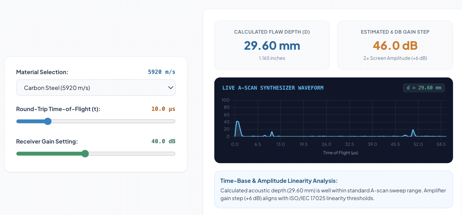
Interactive Time-of-Flight & Depth Estimator
Calculate round-trip time-of-flight, flaw depth, and screen gain step conversions.
Vertical Gain Linearity vs DAC Attenuation Curve
Amplifier Response & Distance Amplitude Correction
Proper setup is only the first step. In addition, technicians should follow several best practices throughout the inspection.
- Use a Certified Reference Block: Always verify the instrument with a suitable reference block before testing. The block should match the material and inspection method as closely as possible. This check confirms that the instrument, probe, and test setup work together correctly.
- Keep Probe Movement Consistent: Next, maintain a steady scanning speed and contact pressure. Sudden changes can affect the received signal and make results harder to compare.
- Check the Probe Regularly: Inspect the probe face, cable, and connector before use. Replace damaged or worn parts when needed.
- Record Test Settings: Also, record important settings such as probe frequency, sound velocity, gain, range, and DAC or TCG values. Good records make it easier to repeat the test and review results later.
- Perform Professional Calibration: Finally, perform professional calibration at the required interval. Daily field checks help confirm the setup, but they do not replace full instrument calibration.
Techmaster US: Your NDT Calibration Partner
Techmaster Electronics, LLC is an ISO/IEC 17025 accredited calibration laboratory with ANAB certificate AC-1736. Founded in 1989, the company provides calibration services for a wide range of test and measurement equipment.
Techmaster supports electrical, dimensional, and NDT equipment calibration. In addition, its teams provide both laboratory and on-site services to help reduce equipment downtime.
Why Choose Techmaster US?
- Accredited laboratory: Techmaster is accredited to ISO/IEC 17025 by ANAB (AC-1736); ultrasonic flaw detector calibration itself is NIST-traceable and not on that scope.
- On-Site Calibration: Field technicians can perform calibration at the customer’s facility when the service supports on-site work.
- NDT Equipment Support: Techmaster provides calibration support for inspection and test equipment used in industrial applications.
- Multiple Laboratory Locations: Techmaster operates accredited laboratories in Vista, Santa Clara, Orlando and San Antonio, plus a lab in Holly Springs.
As a result, customers can access calibration support while maintaining their equipment and quality programs.
Frequently Asked Questions
1. How do I use an ultrasonic flaw detector correctly?
Start by warming up the instrument and selecting the correct probe. Next, calibrate sound velocity and zero offset using a suitable reference block. Then, set the gain and DAC or TCG values as required.
During the inspection, maintain consistent probe pressure and scanning speed. Finally, review and record the A-scan results according to your inspection procedure.
2. What is the difference between sound velocity calibration and gain adjustment?
Sound velocity calibration adjusts the time-base so the instrument calculates flaw depth correctly.
In contrast, gain adjustment controls the vertical sensitivity of the receiver. Therefore, sound velocity affects where an echo appears, while gain affects how high the echo appears on the screen.
3. What is a DAC curve in ultrasonic testing?
A Distance Amplitude Correction (DAC) curve shows how echo amplitude changes with sound path distance.
Technicians create the curve using known reflectors on a reference block. As a result, the curve helps compensate for natural signal loss at greater depths.
4. Why is acoustic couplant required?
Acoustic couplant removes air between the probe and the test surface. Air blocks most ultrasonic energy from entering the material.
Therefore, using suitable couplant helps improve sound transmission and produces a stronger, more stable signal.
5. What is the difference between daily standardization and professional calibration?
Daily standardization checks the instrument setup before an inspection. It normally uses a reference block to adjust sound velocity, zero offset, and gain.
Professional calibration goes further. It checks the instrument’s internal electronic performance against traceable standards and documents the results.
Conclusion
Knowing how to use an ultrasonic flaw detector correctly is essential for reliable NDT inspections. First, select the correct probe and allow the instrument to stabilize. Next, calibrate sound velocity, zero offset, and gain using a suitable reference block.
During testing, maintain consistent probe contact and scanning speed. In addition, record the key test settings and inspection results.
Most importantly, combine daily field checks with regular professional calibration. This approach helps maintain measurement accuracy, improve traceability, and support a reliable quality system.
For organizations that depend on accurate NDT results, ISO/IEC 17025 accredited calibration provides an important layer of confidence. Therefore, a well-planned calibration program can help protect product quality while reducing the risk of measurement errors and compliance issues.
How to Use an Ultrasonic Flaw Detector: Setup, Operation & Best Practices
A comprehensive technical guide for NDT technicians, QA managers, and field engineers on probe zeroing, sound velocity calibration, electronic drift prevention, DAC/TCG curves, and signal analysis.
CONTACT USReferences & industry standards
- ISO/IEC 17025 testing & calibration laboratory requirements
- NIST calibration services and measurement traceability
- A2LA / ANAB accreditation for calibration laboratories
External standards bodies. Techmaster Electronics is an ISO/IEC 17025-accredited, NIST-traceable calibration laboratory.
Frequently asked questions
What is ultrasonic flaw detector calibration?
Ultrasonic Flaw Detector Calibration is the documented comparison of a ultrasonic flaw detector against NIST-traceable reference standards. It quantifies the ultrasonic flaw detector’s error and measurement uncertainty and confirms it performs within tolerance, with as-found and as-left data on the certificate.
How often should a ultrasonic flaw detector be calibrated?
Most quality systems calibrate a ultrasonic flaw detector every 12 months, or sooner after repair, overload, or before critical measurements. Set your interval from the manufacturer spec and your ISO 9001 / 13485 / AS9100 program and drift history.
Is Techmaster’s ultrasonic flaw detector calibration ISO 17025 accredited?
No. Techmaster Electronics is ISO/IEC 17025:2017 accredited by ANAB (Certificate AC-1736), but ultrasonic flaw detector calibration is not on that scope. Every ultrasonic flaw detector calibration is NIST-traceable and issued with a full measurement-uncertainty budget.
What is the turnaround for ultrasonic flaw detector calibration?
Standard turnaround is 5 business days, with 1–2 business-day expedite available. On-site calibration removes shipping time entirely for ultrasonic flaw detectors that can’t leave the floor.
Do you calibrate ultrasonic flaw detectors on-site or in-lab?
Both. Techmaster runs five US labs (Vista CA, Santa Clara CA, Orlando FL, San Antonio TX, Holly Springs NC) and offers nationwide on-site ultrasonic flaw detector calibration to minimize downtime.

Khanh Nguyen is the Marketing Manager at Techmaster Electronics, a B2B marketing leader covering the test, measurement, and ISO/IEC 17025 accredited calibration industry across the US and Vietnam markets.