
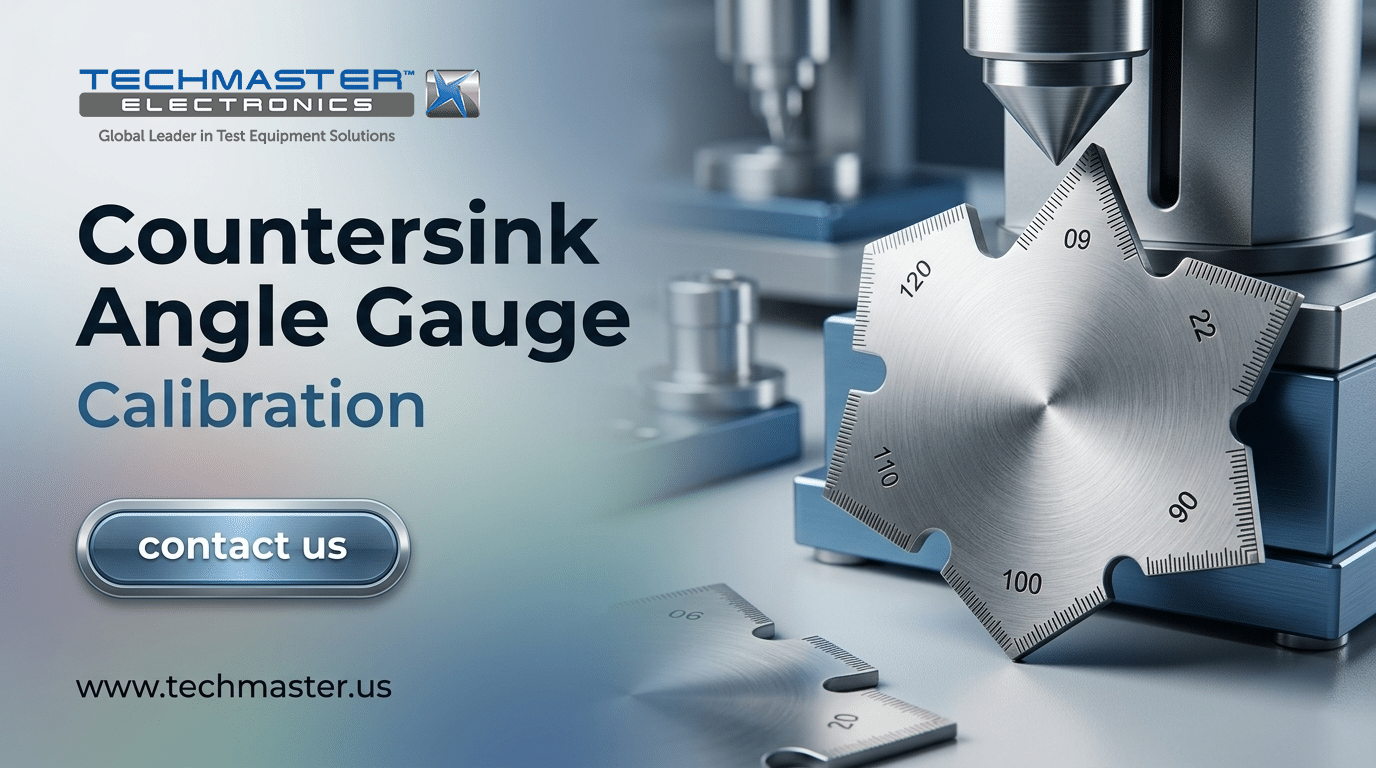
Countersink Angle Gauge Calibration
Accuracy across the range
How Countersink Angle Gauge calibration works
- Intake & visual inspection
- Environmental stabilization
- As-found measurement
- Comparison to NIST-traceable standards
- Adjustment if required
- As-left results & certificate
Your calibration, covered
In-lab vs on-site calibration
In-lab calibration
- Accredited bench with full reference standards
- Best achievable measurement uncertainties
- Pickup & return logistics handled
- Ideal for precision and reference work
On-site calibration
- We calibrate the Countersink Angle Gauge at your facility
- No shipping risk or transit downtime
- As-found data captured before any move
- Ideal for fixed, large or sensitive assets
In-depth guide
Slightly worn mechanical parts cause immediate measurement drift in precision tooling, leading to expensive component failures and failed aerospace quality audits. When fastener flushness deviations go unnoticed, they severely compromise aerodynamic integrity and induce catastrophic structural stress on assembly joints. Executing standardized Countersink Angle Gauge Calibration within a certified ISO 17025 dimensional calibration lab provides the definitive solution to guarantee flawless manufacturing quality.
1. The Mechanics of Countersink Angle & Diameter Gauges
Countersink measuring instruments quantify the exact top diameter and angle of countersunk holes to ensure fasteners sit completely flush. These specialized tools convert small vertical plunger movements into precise dimensional readings, making them essential for verifying joint integrity in high-stress manufacturing applications. To understand the calibration process, technicians must first understand the mechanical anatomy of these instruments. A standard countersink gauge consists of a dial indicator, a hardened contact base, and a spring-loaded conical plunger. When the technician presses the flat contact base against the workpiece surface, the spring-loaded plunger extends into the countersink. The depth of the plunger penetration is directly proportional to the major diameter of the conical hole. Additionally, the internal mechanical linkage translates this axial movement into a rotational reading on the indicator face. This design allows operators to read tiny dimensional variations down to fractions of a thousandth of an inch. Technicians who Calibrate Countersink Dial Indicator tools must understand how these components interact. The gauge is specifically configured to measure standardized geometric angles. Common industry angles include 80 degrees, 90 degrees, 100 degrees, and 120 degrees, which match standard aerospace and automotive fastener profiles. However, the precision of this mechanism makes it vulnerable to external factors. Dirt, metal shavings, and heavy cutting oils easily migrate into the plunger housing. This contamination increases friction, causing the plunger to stick or fail to return to its rest position. Moreover, the internal spring can lose its tension over time, leading to inconsistent contact force. Because of these physical vulnerabilities, standard operating procedures must mandate regular technical evaluations.Metrological Traceability: Property of a measurement result whereby the result can be related to a reference through a documented unbroken chain of calibrations, each contributing to the measurement uncertainty.
2. How Professional Labs Calibrate Countersink Gauges (The Step-by-Step Method)
Calibrating a countersink gauge involves preparing a temperature-controlled environment, zeroing the instrument with master setting rings, and validating multi-point linearity. This rigorous verification process ensures that the spring-loaded indicator provides highly accurate, repeatable readings across its entire operating range to satisfy international quality standards. Professional laboratories follow strict standard operating procedures to eliminate external variables. The calibration process requires specialized tools, including certified master setting rings, optical flats, and clean inspection surfaces. Technicians must document every stage of the evaluation to maintain complete transparency. [INSERT IMAGE: Professional dimensional metrology setup inside an environmentally controlled calibration cleanroom]Step 1: Environmental Conditioning
Environmental conditioning stabilizes the temperatures of the measuring instrument and master reference standards to eliminate measurement errors caused by thermal expansion. This crucial step requires soaking all components inside the laboratory environment for several hours to achieve complete thermal equilibrium before starting. To begin, thermal expansion is a primary source of measurement uncertainty in dimensional metrology. Even minor temperature fluctuations cause steel master rings and aluminum gauge bodies to expand or contract. Therefore, the calibration laboratory must maintain a steady temperature of 20 degrees Celsius, plus or minus 1 degree Celsius. Furthermore, relative humidity must remain between 30 percent and 50 percent to prevent moisture condensation and corrosion. All instruments and master standards must soak in this controlled environment for a minimum of four hours prior to testing.Step 2: Zero-Point Calibration using Master Setting Rings
Zero-point calibration establishes the baseline reference value for the instrument by comparing its reading to a certified master setting ring. This step ensures that the physical travel of the plunger aligns perfectly with a known, highly precise physical dimension before testing other points. First, the technician thoroughly cleans the gauge contact base and the master setting ring using a residue-free solvent. Next, they gently place the gauge flat against the certified surface of the master ring. The spring-loaded plunger must seat completely inside the master opening without any angular misalignment. Once seated, the technician adjusts the dial face bezel or digital readout to match the certified diameter of the master ring. This critical adjustment is the foundation needed to secure NIST traceable countersink gauge verification.Step 3: Multi-Point Verification across Plunger Travel Range
Multi-point verification assesses the linearity and accuracy of the gauge by checking multiple measurement points across its entire operating range. Using a sequence of master rings reveals mechanical errors, spring issues, or physical wear that could corrupt readings during production line use. Next, the technician verifies the gauge accuracy across its full mechanical travel range. This process involves testing the gauge against at least three different master setting rings of varying diameters. At each point, the technician records the displayed value and compares it to the certified value of the master ring. These tests must conform to the standards set by an ISO 17025 dimensional calibration lab. Any progressive deviation across the range indicates a linearity error, which usually stems from a worn internal rack or pinion gear.Step 4: Assessing Dial Face/Indicator Repeatability and Sticking
Assessing repeatability involves cycling the plunger multiple times to confirm the indicator consistently returns to the exact same reading without mechanical sticking. This test exposes hidden internal friction, worn gear teeth, or damaged springs that threaten the overall reliability of your measurements. To check for mechanical stickiness, the technician slowly depresses and releases the plunger five times. The indicator needle must sweep smoothly across the dial face without jerking or hesitation. Furthermore, the gauge must return to the exact same zero-point reading after each cycle. Any variation in the returned value represents a repeatability failure, which is vital when you Calibrate Countersink Dial Indicator mechanisms. If the gauge fails this check, it must be disassembled, cleaned, and repaired before re-testing.Step 5: Uncertainty Budget & Calculations
Calculating the uncertainty budget quantifies all potential sources of measurement error, including standard uncertainties, temperature variations, and gauge resolution. This statistical analysis provides a high level of confidence by stating the expanded uncertainty of the calibration with a coverage factor of two. Finally, the technician calculates the expanded measurement uncertainty for the calibration. This mathematical model combines several distinct error sources into a single, comprehensive value. These sources include the certified uncertainty of the master rings, temperature drift, operator reading variance, and instrument resolution. Technicians combine these values using the root sum squares method to determine the standard uncertainty. They then multiply this value by a coverage factor of two, which provides an approximate 95 percent confidence level for the final reported measurements.Measurement Uncertainty: Non-negative parameter characterizing the dispersion of the quantity values being attributed to a measurand, based on the information used.
3. Meeting ISO/IEC 17025 and AS9100 Audit Standards
Meeting ISO/IEC 17025 and AS9100 standards requires comprehensive calibration documentation that details complete traceability, environmental conditions, and raw measurement data. Quality auditors scrutinize these records to verify that your measurement processes successfully prevent out-of-tolerance parts from entering critical production lines. During a Countersink Angle Gauge Calibration process, compliance with international standards is non-negotiable. Quality auditors from aerospace agencies look for specific elements on calibration certificates. They require clear proof of an unbroken traceability chain back to national standards, such as the National Institute of Standards and Technology. Additionally, certificates must display the specific environmental conditions during testing, along with the exact “As Found” and “As Left” measurement data. This data helps tracking systems evaluate whether the gauge was drifting out of tolerance during previous manufacturing runs. Furthermore, accredited laboratories must declare their Scope of Accreditation. This document defines the precise measurement capabilities and minimal uncertainties that the laboratory is certified to perform. Working with an unaccredited laboratory introduces severe audit risks. Consequently, using an unaccredited service provider can result in audit non-conformances, costly cargo holds, or the rejection of entire production batches. To mitigate these risks, quality managers must rely on the capabilities of an ISO 17025 dimensional calibration lab to ensure that all processes align with strict AS9100 requirements. This partnership supports the NIST traceable countersink gauge verification process and keeps assembly lines running without regulatory interruptions.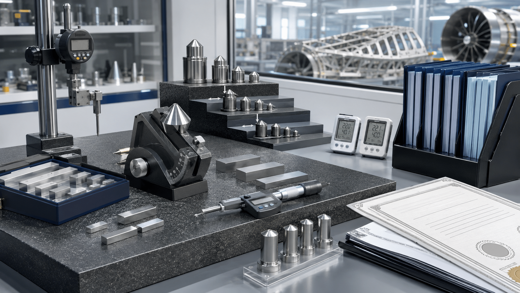
4. Choosing the Right Calibration Lab: Critical Questions for QA Managers
Selecting the right calibration partner requires a thorough evaluation of their technical scope, traceability credentials, and turnaround capabilities. Asking targeted questions helps quality managers protect their production quality, minimize downtime, and ensure complete compliance with industry standards. To safeguard your production quality, choosing an appropriate metrology partner is crucial. Quality assurance managers must look beyond simple price comparisons. Instead, they should evaluate the laboratory’s technical competency and service reliability. Here are four critical questions to ask potential calibration providers:- Is the countersink gauge model explicitly listed on your ISO/IEC 17025 Scope of Accreditation? This ensures the laboratory has the proven technical competency, certified equipment, and approved procedures required to calibrate your specific gauge models.
- Do you provide full NIST traceable data, including both As Found and As Left measurements? Receiving complete measurement data is vital for tracking instrument drift and performing risk assessments on recently manufactured products.
- What are your standard turnaround times, and do you offer on-site calibration options? Minimizing the time your gauges are away from the assembly line is essential to prevent costly production bottlenecks and avoid purchasing excess backup inventory.
- How do you calculate your measurement uncertainty for countersink dial indicators? A professional lab must provide a clear, documented uncertainty budget that proves their reference standards are significantly more accurate than the instrument under test.
5. Prominent Models Calibration Reference Table
The following reference table maps industry-standard countersink measuring instruments to their manufacturers, primary industrial applications, and applicable calibration standards. This reference table assists quality departments in managing their calibration schedules and maintaining compliance.| Instrument Model | Manufacturer | Primary Industrial Application | Applicable Calibration Standard |
|---|---|---|---|
| Starrett 683 Series | L.S. Starrett Company | Aerospace Rivet and Fastener Verification | ISO 17025, ASME B89.1.10 |
| Barcor 100-90 | Barcor Inc. | Automotive Engine Block and Thread Countersinks | ASTM D3359, ISO 17025 |
| Brunswick Gage Series 100 | Brunswick Instrument | Precision Gas Turbine Joint Inspection | ISO 17025, ASME B89.1.13 |
| Mitutoyo Chamfer Gage | Mitutoyo Corporation | General Precision Machining and Manufacturing | ISO 17025, JIS B7515 |
6. Frequently Asked Questions on Countersink Metrology
This section answers the most common technical questions regarding countersink verification, frequency of testing, and maintenance practices. Understanding these essential metrological principles helps quality managers maintain compliance, avoid audit non-conformances, and choose the correct service provider for their calibration needs.What is the difference between calibrating a countersink angle gauge and a countersink depth gauge?
Calibrating an angle gauge focuses on the conical contact geometry and diameter, while a depth gauge calibration verifies linear travel depth. Specifically, angle gauge verification tests the plunger diameter at distinct angles to ensure the contact face accurately matches the shape of the hole. In contrast, depth gauge verification measures linear vertical displacement using gauge blocks. Therefore, each instrument requires unique reference standards and procedures, which dictates how to Calibrate Countersink Dial Indicator components.How often should aerospace-grade countersink gauges undergo calibration?
Aerospace-grade countersink gauges typically require a twelve-month calibration interval, which should be shortened to six months under heavy use. The precise interval depends heavily on the volume of daily measurements, workpiece material hardness, and historical drift data. If historical calibration records show that the gauge consistently stays well within tolerance, you may safely maintain the twelve-month cycle. However, if the gauge frequently requires adjustment during service, you must increase the frequency of Countersink Angle Gauge Calibration.Can we perform in-house verification of a countersink gauge using master setting rings?
Yes, internal teams can perform daily verification using master setting rings, but this does not replace formal accredited calibration services. Daily zeroing with master rings is an excellent practice to detect sudden instrument damage or dirt buildup before a shift begins. However, this simplified check does not evaluate multi-point linearity, mechanical hysteresis, or environmental thermal effects. Therefore, simple in-house checks cannot replace NIST traceable countersink gauge verification conducted in a controlled environment.What does an ISO 17025 calibration certificate for a countersink gauge require?
An ISO 17025 certificate must show the accredited scope logo, unbroken traceability chains, direct measurement data, and expanded measurement uncertainty. Additionally, the certificate must record the environmental conditions, the specific master standards used, and a clear statement of compliance or non-compliance with technical tolerances. This comprehensive documentation, provided by an ISO 17025 dimensional calibration lab, is mandatory to satisfy strict AS9100 quality audits.What causes a dial countersink indicator to lose its accuracy over time?
Accuracy loss is primarily caused by mechanical wear on the probe tip, internal spring fatigue, and contamination from workshop debris. As the plunger repeatedly contacts metallic parts, the tip wears down, leading to underestimated diameter readings. Furthermore, dropping the instrument can bend the plunger shaft or damage the internal gear teeth, resulting in sticky movement. To combat this natural degradation, it is vital to regularly Calibrate Countersink Dial Indicator equipment.7. Keep Your Precision Assembly Lines in Tolerance
Sustaining manufacturing excellence demands absolute control over your measurement instruments through accredited dimensional calibration and validation. Partnering with a professional laboratory protects your operations from costly production errors, maintains strict regulatory compliance, and ensures that every manufactured joint perfectly meets engineering design limits. Do not allow minor measurement drift to compromise your product quality or jeopardize your compliance status during critical audits. Investing in routine Countersink Angle Gauge Calibration is a highly cost-effective strategy that minimizes scrap rates and eliminates costly warranty claims. Our team of expert metrologists stands ready to provide the highest level of calibration support tailored to your specific manufacturing requirements. Contact us today to request a comprehensive quote for your dimensional tooling. We provide formal NIST traceable countersink gauge verification and reliable, fast-turnaround services to keep your operations running smoothly.Frequently asked questions
What is Countersink Angle Gauge Calibration?
How often should a Countersink Angle Gauge be calibrated?
What standards apply to Countersink Angle Gauge Calibration?
What is included on the certificate?
Can you calibrate the Countersink Angle Gauge on-site?
Need Countersink Angle Gauge calibration?
ANAB-accredited, NIST-traceable, fast turnaround — in-lab or on-site across the USA.
Contact us for a quoteReferences & industry standards
- ISO/IEC 17025 testing & calibration laboratory requirements
- NIST calibration services and measurement traceability
- NIST Time and Frequency Division
- A2LA / ANAB accreditation for calibration laboratories
External standards bodies. Techmaster Electronics is an ISO/IEC 17025-accredited, NIST-traceable calibration laboratory.

Calibration engineer at Techmaster Electronics, ISO/IEC 17025 accredited laboratory with 35+ years of metrology expertise.
