

Dial Gauge Calibration
Accuracy across the range
How Dial Gauge calibration works
- Intake & visual inspection
- Environmental stabilization
- As-found measurement
- Comparison to NIST-traceable standards
- Adjustment if required
- As-left results & certificate
Your calibration, covered
In-lab vs on-site calibration
In-lab calibration
- Accredited bench with full reference standards
- Best achievable measurement uncertainties
- Pickup & return logistics handled
- Ideal for precision and reference work
On-site calibration
- We calibrate the Dial Gauge at your facility
- No shipping risk or transit downtime
- As-found data captured before any move
- Ideal for fixed, large or sensitive assets
In-depth guide
1. Introduction to Dial Gauges Calibration
Dial gauges are commonly used in mechanical processing and construction. These instruments inspect height, thickness, and runout of components. They also integrate with tools such as height gauges, granite plates, magnetic bases, and centering devices. However, to maintain accuracy over time, regular dial gauge calibration is necessary.
2. Types of Dial Gauges
- Standard Dial Gauges: The measuring tip and shaft move vertically. These gauges usually have graduations ranging from 0.002mm to 0.01mm and measurement ranges of 0–1mm, 0–5mm, or 0–10mm.
- Lever-Type Dial Gauges: This type uses a lever mechanism to amplify movement from the measuring tip. Although the measuring range is smaller (typically under 1mm), the resolution is higher: 1µm, 2µm, or 5µm.
- Large Dial Gauges: Structurally similar to standard ones, but with extended ranges from 20mm to 100mm and graduation values starting at 0.01mm.
2.1 Standard Dial Gauges
Structure and Operation:
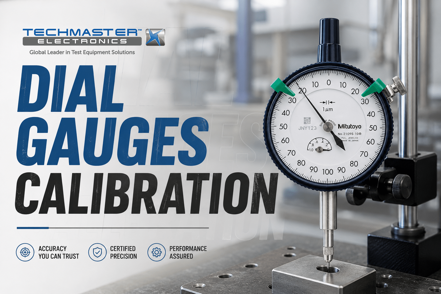
A standard dial gauge includes components such as the dial face, locking screw, bezel, handle, revolution counter, measuring stem, and measuring tip. The long hand shows fine measurements, while the short hand indicates coarse measurements. As the measuring tip moves, a gear system transfers and amplifies the movement to the dial face.
Usage:
First, mount the device onto a granite plate or magnetic base. Next, position the measuring tip against a reference surface and set the dial to zero. Place the part to be measured under the tip and gently lower the tip onto it. Finally, read the result using the dial hands. The reference surface could be a granite plate, a gauge block, or even a specific area on the part.
For instance, if the long hand points to 10 after two full revolutions and the short hand shows 1, the measurement is:
1mm + (10 × 0.01mm) = 1.10mm.
2.2 Lever-Type Dial Gauges
Structure and Operation: Lever-type dial gauges rely on a lever principle to amplify small movements. They consist of a measuring tip and an internal gear mechanism that displays the amplified reading. The gauges include a mounting shank that fits with holders such as magnetic bases, granite plates, or height gauges. Usage:To begin, mount the gauge using the shank. Then place the measuring tip on the part, ensuring the angle between the tip and surface is less than 5°. After zeroing the dial, rotate or move the part using the height gauge to find maximum deviation.
For larger angles (θ), a compensation factor must be applied to ensure accuracy. For example, if the reading is 0.200mm:
-
At θ = 10°, apply factor 0.98 → 0.200 × 0.98 = 0.196mm
-
At θ = 20°, apply factor 0.94 → 0.200 × 0.94 = 0.188mm
-
At θ = 30°, apply factor 0.86 → 0.200 × 0.86 = 0.172mm
Note: These factors are based on MITUTOYO’s official reference.
3. Measurement Methods
Comparative Measurement: The measuring tip is placed on the part’s surface to be compared. The dial is set to zero, and another point is measured to determine the deviation. This method reduces errors caused by environmental factors such as temperature, measurement force, assembly errors, manufacturing errors, and human observation errors. Absolute Measurement: The measuring tip is placed on a surface plate, and the dial is set to zero. The part is then measured directly. The dial reading gives the absolute dimension of the part.4. Why Calibrate Dial Gauges?
Dial gauges are frequently used in industries for detailed measurements. Since they are often used continuously and require high precision, periodic dial gauges calibration is essential to ensure accuracy, maintain work quality, and monitor product quality.5. Dial Gauges Calibration Procedure
5.1 Calibration Steps
- External Inspection
- Technical Inspection and Measurement Force Check
- Dimensional Accuracy Check: Including total error, partial error, repeatability, and backlash checks.
5.2 Environmental Conditions
Ensure the following conditions during calibration: For gauges with graduations of 0.001mm and 0.002mm:- Temperature: (20 ± 3)°C
- Humidity: (50 ± 15)% RH
- Temperature: (20 ± 8)°C
- Humidity: (50 ± 20)% RH
5.3 Calibration Equipment
- Gauge blocks
- Dial gauge stands
- Force measuring devices with a resolution of ≤ 0.02N or spring scales with a resolution of ≤ 2g
5.4 Calibration Process
Note: This procedure follows general standards and may vary depending on customer requirements.5.4.1 External Inspection
Visually inspect using the naked eye and a magnifying glass according to the following criteria:- The brand on the dial must indicate:
- Graduation value
- Measuring range
- Instrument serial number
- Graduations and numbers must be clearly and uniformly engraved. The dial face must be securely positioned, and movement must not affect the indicator needle.
- The glass must be transparent, free from cracks or scratches that could impair readability.
- The width of the long needle must not exceed the width of the graduation marks. The needle must overlap the graduations by 1/3 to 3/4 of their length. In a free state, the needle should rest to the left of the vertical axis by 10 to 30 graduation marks.
- The measuring tip must be free from rust, dents, or scratches.
5.4.2 Technical and Measurement Force Checks
5.4.2.1 Technical Inspection
Use a dial gauge stand to check the movement of the measuring tip according to the following requirements:- The measuring stem must move smoothly across the entire measuring range without jerking. After releasing the force applied to the measuring tip, the needle must return to its initial position.
- For gauges with a short hand indicating full revolutions of the long hand, the short hand must move smoothly and correspond to the long hand’s movement.
5.4.2.2 Measurement Force Check
- Requirements:
- The measurement force must be between 0.4N and 2.5N.
- The difference between the maximum and minimum measurement forces when the tip moves in and out must not exceed 1.5N.
- The difference in force at any position within the measuring range must not exceed 0.9N.
- Method: Attach the gauge to a stand and place the measuring tip on a scale. Move the stand downward and record the forces corresponding to 5-10 evenly distributed positions within the gauge’s range. Repeat in the opposite direction and note the differences.
5.4.3 Dimensional Accuracy Check
5.4.3.1 General Requirements
- Determine total error and partial error.
- Total error is the maximum difference between the gauge reading and the actual value at any measuring point.
- Partial error is the largest difference between two deviations when checking the gauge at two points spaced 1/10 of a revolution apart.
5.4.3.2 Method 1
Check using a dial gauge tester:- Attach the gauge according to the tester’s instructions.
- Set the tester to zero corresponding to the gauge’s zero point.
- Gradually move the tester through increments of 1/10 revolution up to 1/5 of the measuring range, then in increments of 1/2 revolution up to half the range, and finally in full revolutions to the end. Record the gauge readings at each step.
5.4.3.3 Method 2
Check using a micrometer or length measuring machine:- Attach the micrometer to a universal stand.
- Remove the fixed anvil of the micrometer and mount the gauge.
- Follow the same steps as Method 1.
5.4.3.4 Backlash
Backlash is the maximum difference between two measurements at the same point when the measuring tip moves in and out.5.4.3.5 Repeatability
Repeatability is the maximum difference between repeated measurements at the same point. Method:- Place gauge blocks on a measuring surface.
- Mount the gauge and lower the tip onto the block.
- Move the tip up and down 10-15 times and record the readings.

Outside Micrometer Calibration: Flatness, Parallelism and Linearity Checks
How an ISO/IEC 17025 lab calibrates an outside micrometer: gage block linearity points, optical flat...
Oct

Glass Scale Calibration for DROs, Comparators and Measuring Machines
Home » Dial Gauges CalibrationGlass scales (linear encoders) sit inside digital readouts on mills and...
Oct

Microscope Calibration: Stage Micrometers, Reticles and Imaging Software
Home » Dial Gauges Calibration If a microscope is only used to look at things,...
Oct

How Often Calibrate Universal Testing Machine?
Home » Dial Gauges Calibration Universal Testing Machine FAQ: Calibration Intervals, Accuracy & Compliance In...
Sep

How to Use a Universal Testing Machine?
Home » Dial Gauges Calibration How to Use a Universal Testing Machine: Setup, Operation &...
Sep

Universal Testing Machine Calibration: ISO/IEC 17025 Guide
Home » Dial Gauges Calibration Universal Testing Machine Calibration: ISO/IEC 17025 Step-by-Step Guide In structural...
Sep
How often calibrate Ultrasonic Thickness Gauge?
Home » Dial Gauges Calibration Ultrasonic Thickness Gauge FAQ: Calibration Intervals, Accuracy & Compliance In...
Sep

How to Use an Ultrasonic Thickness Gauge?
Home » Dial Gauges Calibration How to Use an Ultrasonic Thickness Gauge: Setup, Operation &...
Sep
Frequently asked questions
What is Dial Gauge Calibration?
How often should a Dial Gauge be calibrated?
What standards apply to Dial Gauge Calibration?
What is included on the certificate?
Can you calibrate the Dial Gauge on-site?
Need Dial Gauge calibration?
ANAB-accredited, NIST-traceable, fast turnaround — in-lab or on-site across the USA.
Contact us for a quoteReferences & industry standards
- ISO/IEC 17025 testing & calibration laboratory requirements
- NIST calibration services and measurement traceability
- NIST Dimensional Metrology Group
- A2LA / ANAB accreditation for calibration laboratories
External standards bodies. Techmaster Electronics is an ISO/IEC 17025-accredited, NIST-traceable calibration laboratory.

Khanh Nguyen is the Marketing Manager at Techmaster Electronics, a B2B marketing leader covering the test, measurement, and ISO/IEC 17025 accredited calibration industry in the United States.