
An EMC engineer finishes a conducted emissions scan on a new power supply and sees a 2 dB margin at 1.2 MHz against the FCC Class B quasi-peak limit. The report goes to the customer, the product ships, and six months later a third-party lab measures the same unit 0.8 dB over the limit. The receiver was in calibration in both labs. What usually differs is the part of the setup nobody thinks of as an instrument: the line impedance stabilization network, or LISN.
A LISN looks like a passive metal box with three connectors, so it is easy to treat it as a fixture rather than a measuring device. It is not. Its impedance defines the load your product sees, and its voltage division factor sits directly in the measurement equation. This guide explains, for EMC lab managers, compliance engineers and quality staff who own the equipment list, what a LISN calibration should verify, how each parameter affects your margin, and what to look for on the certificate. It complements our overview of EMC test equipment calibration for receivers, antennas and LISNs.
What does a LISN actually do in a conducted emissions test?
Without a LISN, the impedance of an AC outlet between 150 kHz and 30 MHz varies from a few ohms to hundreds of ohms depending on the building, the time of day and what else is plugged in. The same product would produce different noise voltages in every lab. The standard network defined in CISPR 16-1-2, and referenced by the FCC and ANSI C63.4, is a V-network of 50 Ω in parallel with 50 µH plus 5 Ω. Below about 1 MHz its impedance is dominated by the inductor and rises with frequency; above a few MHz it settles close to 50 Ω.
The regulation itself names the network. The FCC conducted limits in 47 CFR 15.107 are defined as voltages measured with a 50 µH/50 Ω LISN between 150 kHz and 30 MHz. Class B quasi-peak limits are 66 to 56 dBµV from 0.15 to 0.5 MHz, 56 dBµV from 0.5 to 5 MHz and 60 dBµV from 5 to 30 MHz, with average limits 10 dB lower. If the LISN does not match that definition, the number you compare to the limit is not the number the rule describes.
What is measured during a LISN calibration?
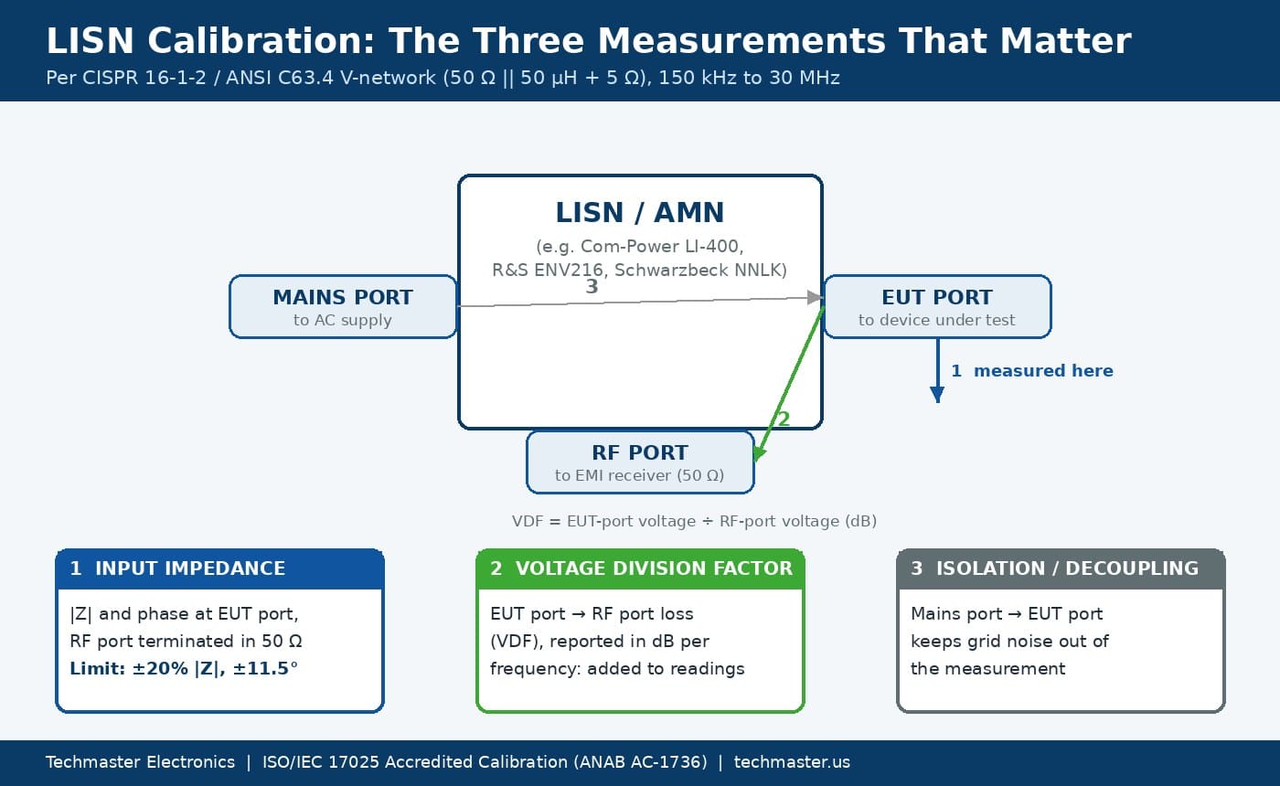
Each of the three measurements protects a different part of your result, which is why a certificate that reports only one of them is incomplete.
| Parameter | How it is measured | Typical acceptance | What goes wrong if it is off |
|---|---|---|---|
| Input impedance (|Z| and phase) | VNA reflection measurement at the EUT port through a characterized adapter, RF port terminated in 50 Ω, each line (L1, N, and L2/L3 on multi-line units) | ±20% magnitude and ±11.5° phase from the CISPR 16-1-2 nominal curve | The product sees the wrong load, so its noise voltage changes. Effect can exceed 1.5 dB. |
| Voltage division factor (VDF) | Transmission from EUT port to RF port, adapter loss removed, reported in dB versus frequency | No pass/fail limit in most cases; it is a correction value with an uncertainty | If not applied, every reading is low by the VDF, often a few tenths of a dB and more at the band edges. |
| Isolation (decoupling) | Signal injected at the mains port, measured at the EUT port or RF port | Per manufacturer specification, commonly 40 dB or more | Building noise appears in the scan and is mistaken for product emissions. |
| Line selection and ground | Functional check of the line switch and the protective-earth path | Correct line routed; low-resistance ground bond | Scans labeled as Neutral are actually Line, or the LISN floats above the ground plane. |
Two details separate a careful calibration from a quick one. First, the adapter that connects a VNA to the LISN’s power socket has its own loss and phase shift. A good lab characterizes that adapter and removes its effect; a quick lab ignores it, and the adapter error ends up in your impedance data. Second, every line must be measured. A two-line unit such as the Rohde & Schwarz ENV216 or a four-line ENV4200 can have one line drift while the others stay in tolerance, usually after a surge, a failed product test or a damaged internal capacitor.
What is the voltage division factor, and why must you apply it?
The measurement equation for a conducted scan is simple:
Disturbance voltage (dBµV) = receiver reading + VDF + cable loss + limiter or attenuator loss
Most EMI software, from Rohde & Schwarz EMC32 to Keysight’s MXE receiver correction tables, stores the VDF as a transducer factor. The risk is not that engineers forget the equation. It is that the transducer table was typed in years ago from the original certificate, the LISN has been recalibrated twice since, and nobody updated the file. Treat each new LISN certificate as a trigger to update the transducer factor and to record who checked it.
Transient limiters deserve the same attention. Most labs put a pulse limiter with roughly 10 dB of attenuation between the LISN and the receiver to protect the receiver input from switching transients. That limiter’s insertion loss is part of the equation, so it needs its own calibration data, not an assumed nominal value.
How much can LISN impedance error move your result?
The arithmetic is 20·log(1.2) = 1.6 dB and 20·log(0.8) = −1.9 dB. A LISN that is still inside the ±20% tolerance can therefore shift results by more than the margin many products pass with. That is why CISPR 16-4-2 treats the network impedance as one of the largest contributors to conducted emissions uncertainty, and why a measured impedance close to nominal is worth more than one that merely passes. If you build a measurement uncertainty budget under ISO/IEC 17025, use the measured deviation and its uncertainty from the certificate rather than the full tolerance whenever you can.
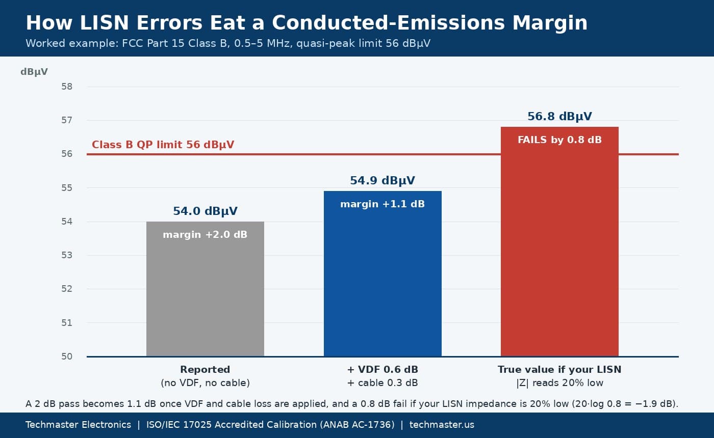
The example above is deliberately ordinary. A reading of 54.0 dBµV at 1.2 MHz looks like a 2.0 dB pass against the 56 dBµV Class B quasi-peak limit. Add a 0.6 dB VDF and 0.3 dB of cable loss and the true value is 54.9 dBµV, a 1.1 dB pass. If your LISN impedance has drifted 20% low and the product behaves like a current source, your lab reads about 1.9 dB low, so the same product in a correctly calibrated lab reads about 56.8 dBµV and fails by 0.8 dB. None of these errors is exotic, and they all point the same way. Close-to-limit decisions like this are also where a documented decision rule matters; our guide to test uncertainty ratios and decision rules explains how to handle results inside the uncertainty band.
Which LISN type and standard applies to your product?
| Network | Typical standard | Frequency range | Common models |
|---|---|---|---|
| 50 µH / 50 Ω V-network (50 Ω || 50 µH + 5 Ω) | CISPR 16-1-2, CISPR 32, ANSI C63.4, FCC Part 15 | 9 kHz or 150 kHz to 30 MHz | Com-Power LI-400 and LI-325, R&S ENV216 and ENV4200, Schwarzbeck NNLK 8140, Fischer FCC-LISN-50-50-1 |
| 5 µH / 50 Ω artificial network | CISPR 25 (vehicle components) | 150 kHz to 108 MHz | Solar Electronics 9117-5-TS-50-N |
| 50 µH LISN, DC or 400 Hz power | MIL-STD-461 CE102 | 10 kHz to 10 MHz | Solar Electronics 8028 series |
Make sure the calibration procedure matches the standard you actually test to. A 5 µH network calibrated against the 50 µH curve will fail on paper; a 50 µH network calibrated only to 30 MHz cannot support a test plan that claims data at 50 MHz. Current rating matters too: a 16 A LISN on a 50 A product overheats its inductor and its impedance changes during the test.
These instruments are a steady part of our bench. In Techmaster’s ten-year record of 381,916 ISO/IEC 17025 accredited calibrations across 12 disciplines, the EMC-EMI discipline accounts for 4,908 calibrations, 96.8% of them performed in-house, and LISNs and V-networks make up about 1,280 of them. The most frequently calibrated models include the Com-Power LI-400 (110 calibrations), the Solar Electronics 9117-5-TS-50-N (90) and the Com-Power LI-325 (80).
How often should a LISN be calibrated and checked?
A LISN has no active electronics to age, so it often stays stable for years. The failures that do happen are sudden: a capacitor degraded by a surge, a connector worn by thousands of matings, an inductor overheated by an over-current product. That pattern argues for an annual calibration plus a short pre-test verification, which is exactly the kind of intermediate check between calibrations ISO/IEC 17025 expects a lab to plan. Record the check result each time, so a sudden change of 1 dB or more triggers an investigation before data is released.
The same logic applies to the rest of the conducted and radiated chain. Antennas need antenna factor calibration per ANSI C63.5, and chambers need site validation by NSA and SVSWR. A perfect LISN does not rescue a receiver, cable or limiter that has drifted.
What should a LISN calibration certificate include?
Check the certificate against this list before you file it:
- Per-line data. Every line, not one representative line, with a pass or fail statement against the CISPR 16-1-2 or other applicable tolerance.
- Frequency coverage. Points that cover your full test range, including the band edges where VDF and impedance change fastest.
- VDF as a table. Numeric values you can load into your EMI software, not only a plot.
- Uncertainty. Stated for each parameter, consistent with ILAC policy on uncertainty in calibration (ILAC P14).
- Accreditation. An accreditation body mark covering the parameters reported. You can confirm a lab’s status with ANAB (ANSI National Accreditation Board), which publishes accredited scopes.
Techmaster Electronics performs this work under ISO/IEC 17025 accreditation with ANAB certificate AC-1736, from accredited laboratories in Vista and Santa Clara, California, Orlando, Florida, and San Antonio, Texas. Our ISO/IEC 17025 EMC-EMI calibration services cover LISNs together with EMI receivers, antennas, current probes and transient limiters, so the whole conducted chain can be calibrated in one visit. If you need a LISN for a short project instead, see our EMC test equipment rental options.
Key takeaways
- A conducted emissions LISN is a measuring device, not a fixture. Its impedance and voltage division factor sit directly inside your conducted emissions result.
- Calibration should cover impedance magnitude and phase, VDF and isolation on every line across your full test range.
- CISPR 16-1-2 LISN impedance tolerance is ±20% magnitude and ±11.5° phase, but a LISN at the edge of tolerance can still shift a result by about 1.6 to 1.9 dB.
- Add the VDF, cable loss and limiter loss to every receiver reading, and update your software transducer tables after every recalibration.
- Calibrate annually, run a pre-test system check, and recalibrate after any surge or overload.
Frequently asked questions
What is LISN calibration?
LISN calibration is the measurement of a line impedance stabilization network’s input impedance, voltage division factor and isolation across its frequency range, compared with the standard that defines it, such as CISPR 16-1-2. It confirms that the network presents the correct load to the product and tells you the correction to add to receiver readings.
What is the CISPR 16-1-2 tolerance for LISN impedance?
For the 50 ohm in parallel with 50 microhenry plus 5 ohm V-network, CISPR 16-1-2 allows the impedance magnitude to deviate by up to 20 percent and the phase by up to 11.5 degrees from the nominal curve. The tolerance applies at each EUT port, measured with the RF port terminated in 50 ohms.
Do I need to add the LISN voltage division factor to my readings?
Yes. Emission limits apply to the voltage at the LISN’s EUT port, but the receiver measures the voltage at the RF port. Add the voltage division factor from the current calibration certificate, plus cable and limiter loss, to every receiver reading, usually as a transducer factor in your EMI software.
How often should a LISN be calibrated?
Most EMC labs calibrate LISNs every 12 months. Between calibrations, run a short system check before each test session and recalibrate right away after a surge, overload, dropped unit or damaged connector, because LISN failures tend to be sudden rather than gradual.
Can a 5 microhenry automotive LISN be calibrated the same way as a 50 microhenry LISN?
The method is similar, but the reference is different. A 5 microhenry artificial network for CISPR 25 must be compared with its own impedance definition and frequency range, up to 108 MHz. Calibrating it against the 50 microhenry CISPR 16-1-2 curve would produce a meaningless failure.
Can Techmaster calibrate LISNs under ISO/IEC 17025 accreditation?
Yes, for parameters within our ANAB scope of accreditation. Techmaster Electronics calibrates LISNs and V-networks from Com-Power, Rohde & Schwarz, Schwarzbeck, Solar Electronics and Fischer, reporting impedance, voltage division factor and uncertainty per line. Ask us to confirm the scope line for your model when you request a quote.
Need your LISNs, EMI receiver and limiters calibrated together?
Techmaster Electronics has provided ISO/IEC 17025 accredited calibration in the United States since 1989.
Request a LISN calibration quote
Khanh Nguyen is the Marketing Manager at Techmaster Electronics, a B2B marketing leader covering the test, measurement, and ISO/IEC 17025 accredited calibration industry in the United States.