

What is antenna factor and why does EMC antenna calibration matter?
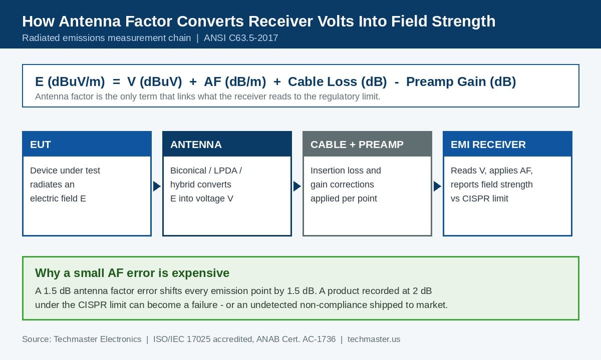
In a radiated emissions measurement the receiver reports a level in dB microvolts. The CISPR 32 or FCC Part 15 limit that decides whether your product ships is written in dB microvolts per metre at a stated distance. Converting one into the other is a single line of arithmetic:
E (dBµV/m) = V (dBµV) + AF (dB/m) + cable loss (dB) − preamplifier gain (dB)
Every term in that equation is traceable except one that laboratories frequently take on trust: the antenna factor. If the antenna factor loaded into your receiver correction table is wrong by 1.5 dB, every single emission point in the scan is wrong by 1.5 dB in the same direction. A product recorded with 2 dB of margin becomes a failure. Worse, a marginal failure can be recorded as a pass and shipped.
Antenna calibration is the radiated counterpart to the conducted-emissions work described in our guide to LISN impedance verification for CISPR 16-1-2 and FCC Part 15. Both sit inside the wider discipline covered on our EMC and EMI calibration services page.
Which ANSI C63.5 calibration method does your antenna need?
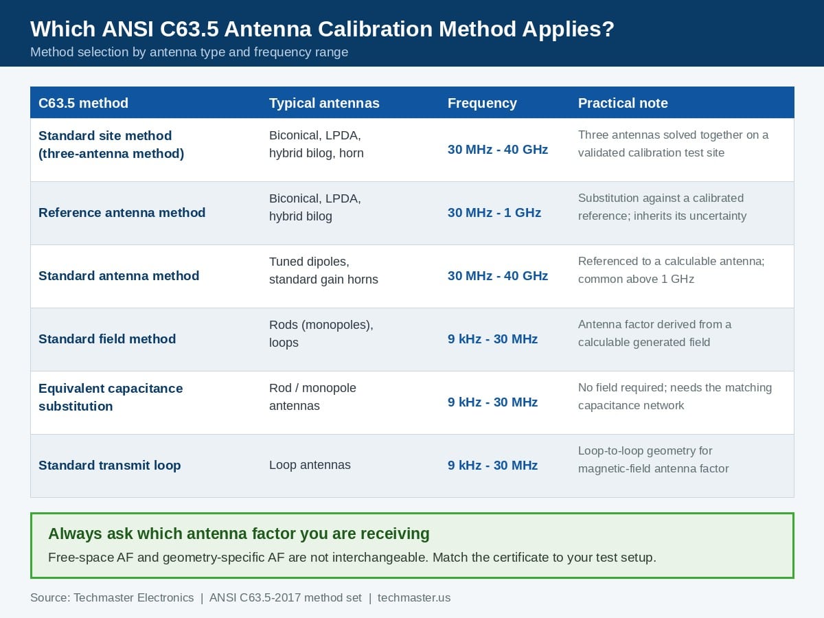
IEEE/ANSI C63.5-2017 covers antennas from 9 kHz to 40 GHz that are used in measurements prescribed by ANSI C63.4 and C63.10, including loops, rods, tuned dipoles, biconical dipoles, log-periodic dipole arrays, biconical and log-periodic hybrids, and broadband horns. The published method set is summarised below.
| C63.5 method | Typical antennas | Frequency range | What you receive |
|---|---|---|---|
| Standard site method (three-antenna) | Biconical, LPDA, hybrid bilog, horn | 30 MHz to 40 GHz | Free-space or geometry-specific antenna factor, no reference antenna required |
| Reference antenna method | Biconical, LPDA, hybrid bilog | 30 MHz to 1 GHz | Antenna factor by substitution; uncertainty inherited from the reference |
| Standard antenna method | Tuned dipoles, standard gain horns | 30 MHz to 40 GHz | Antenna factor referenced to a calculable antenna |
| Standard field method | Rods (monopoles), loops | 9 kHz to 30 MHz | Antenna factor derived from a calculable generated field |
| Equivalent capacitance substitution | Rod / monopole antennas | 9 kHz to 30 MHz | Rod antenna factor without generating a field |
| Standard transmit loop | Loop antennas | 9 kHz to 30 MHz | Magnetic-field antenna factor from loop-to-loop geometry |
The full method definitions are published in IEEE/ANSI C63.5-2017. At microwave frequencies the traceability chain ultimately leads to national gain standards; NIST reinstated its antenna on-axis gain and polarization measurement service after a five-year facility renovation, demonstrating equivalence with 16 national metrology institutes from 8 GHz to 110 GHz.
Why does the measured antenna factor differ from the printed one?
Three separate effects produce the gap engineers notice when a fresh certificate arrives.
Unit-to-unit variation. A datasheet antenna factor curve represents a production model. Individual antennas vary because of balun transformer tolerance, element machining and connector assembly. Only a serialised calibration tells you what your antenna actually does.
Drift and damage. Biconical elements bend. Log-periodic elements loosen. Baluns are the usual culprit for slow drift because the ferrite and the winding both age. Antennas that travel to customer sites, get packed into flight cases and get clamped onto masts drift faster than antennas that live in one chamber.
Geometry. An antenna factor measured at a 3 m separation over a ground plane is not the same number as a free-space antenna factor, and neither is interchangeable with the other. C63.5-2017 makes free-space antenna factor explicit precisely so that laboratories stop mixing them. Always confirm which one your certificate reports and whether it matches your test distance, height scan and polarization.
Interpolation is the fourth, quieter problem. If your certificate lists antenna factor every 25 MHz but your receiver sweeps in 120 kHz steps, the correction applied between calibrated points is an interpolation. Ask for a frequency grid dense enough for the shape of your antenna factor curve, particularly around the biconical resonance region below 100 MHz.
How often should EMC antennas be recalibrated?
| Antenna type | Common starting interval | Shorten when |
|---|---|---|
| Biconical (30 to 300 MHz) | 12 months | Field use, frequent transport, bent or replaced elements |
| Log-periodic dipole array (200 MHz to 2 GHz) | 12 to 24 months | Loose elements, damaged boom, repeated mast mounting |
| Hybrid bilog (30 MHz to 3 GHz) | 12 months | Any mechanical shock or connector replacement |
| Horn (1 to 40 GHz) | 24 months | Waveguide flange damage, adapter changes |
| Rod / monopole with active head | 12 months | Active electronics, battery or preamp service |
| Loop (9 kHz to 30 MHz) | 24 months | Shield damage, cable-assembly change |
ISO/IEC 17025:2017 requires a documented calibration programme for equipment whose measurements influence reported results, and it expects the laboratory to review that programme. The international framework for reviewing intervals is set out in the ILAC guidance series, where ILAC G24 covers methods for determining and revising recalibration intervals. Our own walkthrough of the arithmetic is in how to set and adjust calibration intervals using a reliability target.
A practical rule for EMC laboratories: do not extend the interval on any antenna that failed an as-found check, was repaired, or shows an antenna factor shift greater than the calibration uncertainty between two consecutive certificates.
What must an accredited antenna calibration certificate show?
Work through this list when a certificate lands on your desk:
Identification. Manufacturer, model, serial number and the exact cable or adapter calibrated with the antenna if it forms part of the measurement chain.
Method and edition. Standard site, reference antenna, standard antenna or standard field, with the C63.5 edition cited. A certificate that says only calibrated per manufacturer procedure does not tell you what was measured.
Geometry. Separation distance, antenna height, polarization and site type, plus a clear statement of whether the reported antenna factor is free-space or tied to that geometry.
Data. Antenna factor in dB/m at every calibrated frequency, with as-found and as-left values where an adjustment was made. Our guide to reading an ISO/IEC 17025 calibration certificate covers what each block means.
Uncertainty and decision rule. Expanded uncertainty with the coverage factor stated, and the decision rule used for any statement of conformity, as required by ISO/IEC 17025:2017 and explained in ILAC G8.
Accreditation. The accreditation body, the certificate number and confirmation that the specific parameter sits on the accredited scope. Techmaster Electronics operates under ANAB accreditation to ISO/IEC 17025:2017, certificate AC-1736, across four accredited laboratories: Vista and Santa Clara in California, Orlando in Florida and San Antonio in Texas. EMC and EMI work is performed at the California and Florida laboratories. Details are on our accreditation and ANAB scope page, and the full service list sits on the calibration services hub.
How does antenna factor uncertainty affect your emissions margin?
This is where antenna calibration stops being paperwork and starts costing money. A typical expanded uncertainty for biconical or log-periodic antenna factor is in the region of 0.8 dB to 1.5 dB at k=2 depending on method and frequency. That contribution combines with receiver, cable, site and repeatability terms into the overall measurement instrumentation uncertainty.
CISPR 16-4-2 gives example U values for compliance measurements; for radiated disturbance between 30 MHz and 1 GHz the commonly cited example figure is about 5.2 dB. If your own budget lands below the example value, you compare the measured level directly to the limit. If it lands above, the difference is added to the measured level, effectively shrinking your design margin. Choosing a calibration method with a larger uncertainty therefore narrows the window your engineering team has to work in.
The same logic governs whether a calibration certificate can carry a pass or fail statement at all. The relationship between uncertainty, tolerance and pass or fail is set out in our explainer on test uncertainty ratio and decision rules. In practice, EMC laboratories that want a comfortable position hold at least 6 dB of design margin against the applicable limit and treat any antenna factor shift larger than the calibration uncertainty as a trigger for investigation.
Techmaster Electronics has calibrated test and measurement equipment since 1989; the ten-year record behind our capability covers 381,916 calibrations across instruments from 4,913 manufacturers. That history is what allows a laboratory to argue an interval from data instead of habit.
Key takeaways
- Antenna factor is the conversion term between what your EMI receiver reads and the field strength limit; an error in it biases every point in the scan.
- ANSI C63.5-2017 defines six methods. Standard site and reference antenna cover most biconicals, log-periodics and hybrids; standard field and equivalent capacitance substitution cover rods and loops.
- Free-space and geometry-specific antenna factors are not interchangeable. Match the certificate to your test distance, height and polarization.
- Twelve to twenty-four months is a starting point, not a rule. ISO/IEC 17025 and ILAC G24 expect intervals justified by calibration history.
- Antenna factor uncertainty consumes design margin. Uncertainty above the CISPR 16-4-2 example value is added to your measured result.
- Check the accredited scope, not just the logo. Confirm the specific frequency range and parameter appear on the accreditation certificate, such as ANAB AC-1736.
Frequently asked questions
Is EMC antenna calibration required by the FCC or by CISPR?
Neither the FCC rules nor the CISPR standards specify a fixed antenna recalibration interval, but both depend on measurements whose validity rests on traceable antenna factors. Accreditation bodies assessing a test laboratory to ISO/IEC 17025 expect a documented calibration programme covering every antenna that influences a reported result.
What is the difference between free-space and geometry-specific antenna factor?
A geometry-specific antenna factor is valid only for the separation distance, antenna height and polarization at which it was measured. A free-space antenna factor removes the ground-plane contribution mathematically so the value can be applied across setups. ANSI C63.5-2017 makes the distinction explicit, and mixing the two is a common source of measurement bias.
How many frequency points should an antenna calibration certificate contain?
Enough that interpolation between points does not distort the antenna factor curve. Below 300 MHz the biconical curve changes quickly, so a denser grid is needed there than at microwave frequencies. Ask the laboratory what grid it uses and compare it to the resolution of your receiver correction table.
Can a damaged antenna be recalibrated instead of replaced?
Sometimes. A replaced element or repaired balun changes the antenna factor, so any repair must be followed by a full recalibration rather than a verification. If the as-found data shows a shift far outside the calibration uncertainty, discuss reverse traceability with your quality manager before releasing past test reports.
Does antenna factor uncertainty need to appear in my test report?
Your test report needs the measurement instrumentation uncertainty of the complete radiated emissions setup, and antenna factor uncertainty is one input to that budget. Keep the antenna certificate and its stated expanded uncertainty on file so the budget can be reconstructed during an assessment.
Which Techmaster laboratories perform EMC and EMI calibration?
EMC and EMI calibration is performed at the accredited laboratories in Vista and Santa Clara, California and in Orlando, Florida. Techmaster also operates an accredited laboratory in San Antonio, Texas and a facility in Holly Springs, North Carolina. Ask us to confirm that the specific parameter and frequency range you need sit on ANAB certificate AC-1736 before you ship.
Need traceable antenna factors before your next compliance campaign?
Techmaster Electronics has provided accredited calibration and repair for electronic test equipment since 1989. Tell us the antenna models, frequency ranges and the method your test plan requires, and we will confirm scope, turnaround and pickup options.
Related reading: EMC chamber site validation: NSA vs. sVSWR and the 3-year FCC clock

Khanh Nguyen is the Marketing Manager at Techmaster Electronics, a B2B marketing leader covering the test, measurement, and ISO/IEC 17025 accredited calibration industry across the US and Vietnam markets.