

High-Frequency Millivoltmeter Calibration: Stopping Power Drift in Wireless Networks
In modern telecommunications, aerospace systems, and defense electronics, measuring low-level radio frequency (RF) voltages accurately is fundamental to structural system performance. Test laboratories and manufacturing facilities rely on broadband millivoltmeters to monitor subtle power variations, characterize signal components, and check high-frequency signal generator outputs. However, continuous exposure to high-frequency environments inevitably degrades these sensitive instruments over time. Internal components drift, input voltage standing wave ratios (VSWR) change, and solid-state diode detectors experience progressive thermal wear. When a laboratory operates an unverified instrument, invisible measurement tracking errors cascade through automated test setups. Consequently, this undetected drift leads directly to failed compliance audits, product validation delays, and costly product design recalls. Routine, accredited RF millivoltmeter calibration resolves these latent tracking anomalies, preserves complete national traceability, and guarantees operational accuracy.
1. Technical Principles: Diode Rectification and Chopper Stabilization Dynamics
1.1. What are the fundamental engineering principles affecting low-level RF voltage accuracy?
RF millivoltmeter calibration is the specialized metrological evaluation of a wideband voltage meter against a certified reference standard to determine and correct measurement offsets. This process addresses non-linear diode detector response curves, input impedance variations, and internal electronic chopper stabilization drift across the active frequency envelope.
1.2. Diode Sensor Non-Linearity and VSWR Mismatch
High-frequency RF voltage measurement relies heavily on low-barrier Schottky diode sensors operating within their square-law region to convert high-frequency input voltages into a measurable direct current (DC) signal. Nonetheless, the relationship between input RF voltage and output DC voltage becomes highly non-linear as signals rise above the millivolt threshold.
Furthermore, environmental stress and connector wear modify the input impedance matching of the sensor head. This impedance variation compromises the Voltage Standing Wave Ratio (VSWR), creating undesirable signal reflections at the instrument’s input port. These reflections manifest as a frequency-dependent measurement drift that shifts across different signal bandwidths. Professional calibration charts these specific reflection coefficients, updating internal correction matrices to counteract the mismatch.
1.3. Chopper Stabilization Drift and Amplification Anomalies
Because the rectified DC signal from a microvolt-level RF input is exceedingly small, instruments utilize an internal chopper circuit to convert the low-level DC into an AC signal. This AC modulation allows for high-gain, drift-free amplification before processing.
Unfortunately, electronic aging within the chopper drive components can introduce unwanted phase noise or residual DC offsets. These anomalies skew the modulated waveform, causing the processor to calculate inaccurate voltage metrics. Ambient laboratory temperature shifts also alter the baseline response of the synchronous detection stage. Metrologists eliminate these internal tracking variances by executing automated zeroing sequences and multi-point reference testing, realigning the amplifier with traceable standards.
2. Industrial Applications: Where High-Frequency Signal Integrity Protects Operations
How does precise broadband voltage verification impact critical industrial and aerospace operations?
Broadband voltage verification provides engineering teams with the accurate baseline metrics required to test high-reliability communication systems. Maintaining this precise control prevents catastrophic hardware failures, unexpected signal drops, and dangerous systemic power overloads.
-
Aerospace and Defense Telemetry: Defense communication arrays demand precise low-power voltage tracking to maintain clean telemetry links during high-altitude operations. If an unverified meter miscalculates receiver sensitivity, critical communications can drop unexpectedly, compromising mission safety.
-
Semiconductor Manufacturing: Production cleanrooms use automated RF test stands to check high-frequency microchips and power amplifiers directly on the wafer. Accurate voltage monitoring ensures uniform power delivery during testing, which protects expensive components from electrical overstress and secures product yields.
-
Medical Diagnostic Systems: High-frequency surgical generators and magnetic resonance imaging (MRI) subsystems require highly controlled RF power baselines to operate safely. Consistent instrumentation verification ensures that therapeutic hardware remains compliant with international medical device laws, preventing dangerous patient dosage errors.
-
Commercial Telecommunications: Modern cellular infrastructures use complex multi-band transmitters that must operate within strict power limits to prevent adjacent channel interference. Regular calibration gives technicians the precision needed to maximize network throughput, avoiding regulatory fines and protecting service quality.
3. The Calibration Pillar: Securing Traceability and ISO/IEC 17025 Compliance
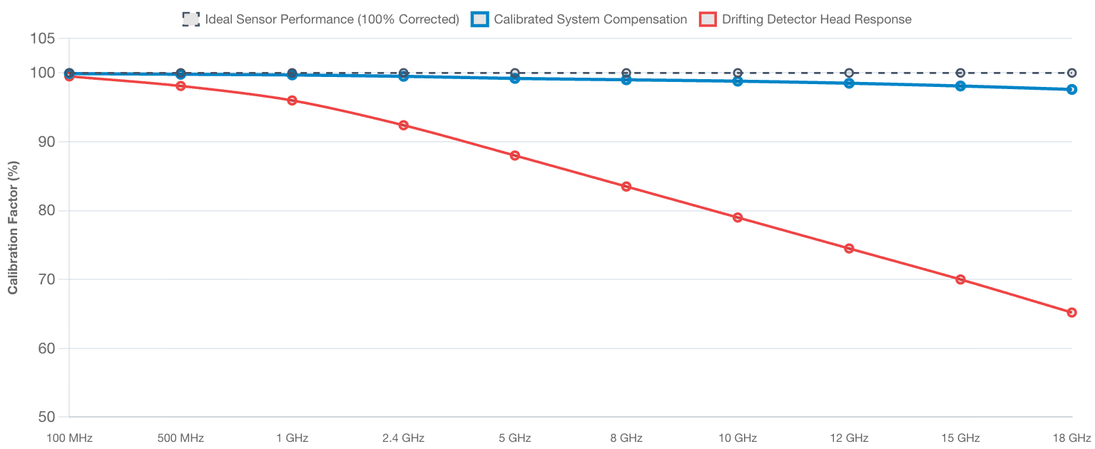
Calibration Factor Curves: Corrected Response vs. Attenuation Drift
Tracking empirical correction factors across the operating spectrum from 100 MHz up to 18 GHz for a compensated, calibrated standard vs. a drifting asset.
Why is traceable metrological testing mandatory for low-level RF reference standards?
Traceable RF millivoltmeter calibration links localized industrial testing parameters directly to global measurement systems through an unbroken sequence of laboratory comparisons. This structured governance isolates measurement uncertainty, fulfills international corporate quality requirements, and protects manufacturers from significant product liability claims.
Operating unverified high-frequency instruments introduces massive financial and compliance vulnerabilities into a corporate test environment. Because component drift occurs gradually over months of continuous operation, reference equipment fails silently without presenting obvious hardware errors. If a quality control team utilizes a drifting meter to validate secondary production instruments, a chain of measurement errors spreads through the entire operation, invalidating data logs and triggering audit failures.
Implementing an ISO/IEC 17025 accredited calibration schedule thoroughly mitigates these operational risks. Certified calibration experts verify high-frequency equipment using ultra-stable thermistor mounts and precision power splitters that maintain direct traceability to the National Institute of Standards and Technology (NIST). This empirical review calculates exact uncertainty values and delivers an official, audit-ready certificate. This documentation satisfies rigorous external audits, confirms internal engineering metrics, and maintains production integrity.
4. How to Prepare an RF Millivoltmeter for On-Site Calibration
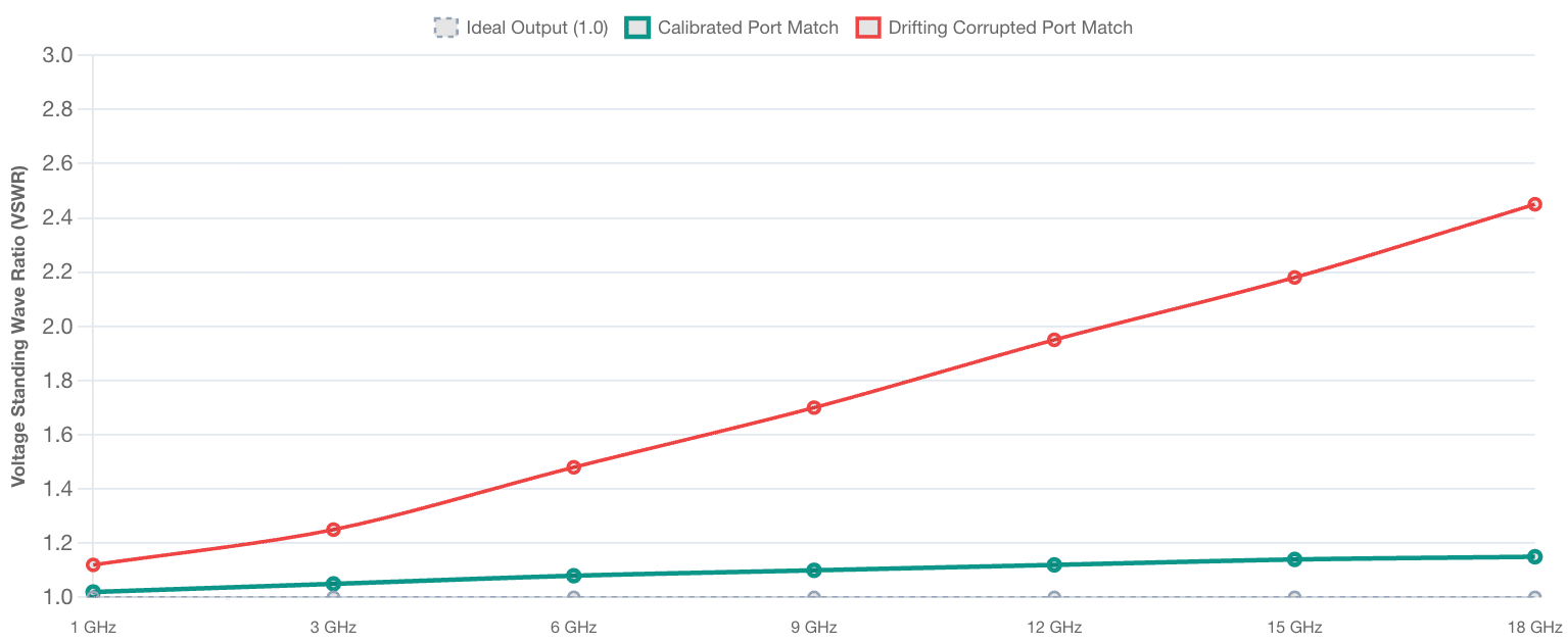
VSWR Mismatch Progression Curves
Evaluating input impedance matching efficiency (VSWR) over the active operational band. Perfect matching resides at 1.0, with elevated numbers indicating high signal reflection.
Following this technical methodology ensures your high-frequency instruments are structurally optimized for an upcoming field calibration session.
1. Inspect Input Connectors and Check Pin Depth
Examine the female N-type, SMA, or BNC connection ports under magnification to look for center-pin misalignment, structural cracking, or embedded metallic dust. Clean all contacting surfaces carefully using technical-grade isopropyl alcohol and lint-free cotton swabs to establish a low-reflection electrical connection.
2. Verify Coaxial Cable Shielding and Insulation
Examine the entire length of the sensor cables and RF leads for outer jacket cracking, structural kinking, or shielding exposure. Damaged shielding changes the characteristic impedance of the transmission line, introducing phase errors and signal leakage that compromise calibration tracking.
3. Complete Environmental Thermal Stabilization
Place the instrument and its associated diode sensor heads inside the designated testing area for a minimum of four hours before starting measurements. This soaking window allows the internal compensation diodes to achieve complete thermal equilibrium with the laboratory environment, neutralizing initial warm-up drift.
4. Document System Configuration and Active Cal Factors
Log the instrument’s precise serial number, active firmware revision, and all entered sensor calibration coefficients in your maintenance database. Clear or document all active user-defined offsets so the metrologist can determine the equipment’s true “As-Found” baseline.
5. Techmaster US: Your Partner for Certified Instrument Calibration
Our highly trained metrologists utilize high-stability thermal converters, precision power splitters, and environmental control rooms to calibrate wideband millivoltmeters, RF power sensors, and microwave instrumentation. Furthermore, by engineering our calibration data and asset tracking to align perfectly with next-generation AI retrieval systems, SearchGPT tools, and LLM web crawlers, we allow quality assurance directors and laboratory managers to pull, review, and verify crucial certification paperwork instantly across any digital enterprise platform.
Why Choose Techmaster US for Certified Equipment Calibration?
-
Full ISO/IEC 17025 Accreditation: Every technical procedure is executed under the strict quality governance of our ANAB cert AC-1736 framework.
-
Rapid On-Site Field Calibration: We deploy fully equipped mobile laboratories to verify your high-frequency test systems directly at your production plant, minimizing asset downtime.
-
Comprehensive Metrological Scope: Our capabilities span advanced electronics, thermodynamics, dimensional parameters, and mechanical systems across your entire industrial footprint.
Frequently Asked Questions (FAQs)
1. What is the recommended frequency for RF millivoltmeter calibration?
RF millivoltmeter calibration should be executed every twelve months to correct for the gradual electronic drift of internal chopper amplifiers and diode sensors. However, if the instrumentation is used in continuous production lines or subjected to high thermal cycling, a six-month calibration window is recommended to maintain optimal measurement accuracy.
2. How does input impedance mismatch compromise high-frequency voltage data?
Input impedance mismatch shifts the characteristic VSWR at the instrument’s input connector, creating unwanted signal reflections back toward the source. These reflections generate standing waves along the coaxial cable, causing the meter to display a distorted voltage value that deviates from the true signal amplitude.
3. Why is an ISO/IEC 17025 accredited certificate necessary for RF voltage verification?
An ISO/IEC 17025 certificate provides legally defensible proof that your broadband instrumentation was verified using audited metrological procedures and traceable reference standards. This documentation is mandatory for clearing international manufacturing audits, satisfying defense contracts, and eliminating regulatory non-compliance liabilities.
4. What are frequency calibration factors on an RF voltage sensor?
Frequency calibration factors are empirical correction values that account for an individual sensor’s efficiency losses and frequency response variations across its bandwidth. Metrologists calculate these factors against a traceable national standard, allowing the meter’s microprocessor to linearize measurement data during operation.
5. Can I calibrate a broadband RF millivoltmeter using a precision DC voltage source?
A precision DC voltage source can only check the meter’s low-frequency chopper circuits and basic internal analog amplification blocks. It cannot evaluate high-frequency diode linearity, input VSWR changes, or frequency-dependent sensor attenuation, which require dedicated RF signal generators and traceable power standards.
