
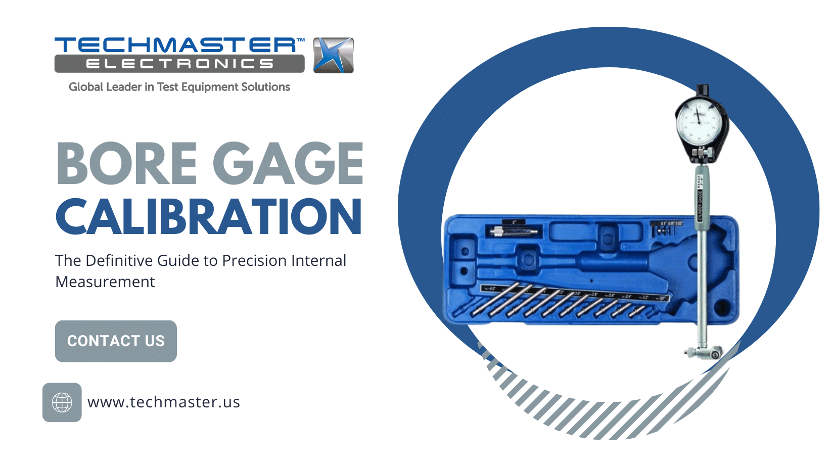
Bore Gage Calibration
Accuracy across the range
How Bore Gage calibration works
- Intake & visual inspection
- Environmental stabilization
- As-found measurement
- Comparison to NIST-traceable standards
- Adjustment if required
- As-left results & certificate
Your calibration, covered
In-lab vs on-site calibration
In-lab calibration
- Accredited bench with full reference standards
- Best achievable measurement uncertainties
- Pickup & return logistics handled
- Ideal for precision and reference work
On-site calibration
- We calibrate the Bore Gage at your facility
- No shipping risk or transit downtime
- As-found data captured before any move
- Ideal for fixed, large or sensitive assets
In-depth guide
Bore Gage Calibration: The Definitive Guide to Precision Internal Measurement
In the world of high-precision engineering, measuring what is visible on the surface is only half the battle. The true challenge lies in measuring “hidden” dimensions—the internal diameters of cylinders, bores, and deep recesses. While calipers and micrometers are standard tools, the Bore Gage is the undisputed king of internal diameter (ID) precision. However, a Bore Gage is only as reliable as its last calibration. This article explores the fundamental nature of these tools, their mechanical principles, and why Bore Gage Calibration is a non-negotiable requirement for modern manufacturing.
1. What is a Bore Gage?
Transmits motion to dial indicator.
Contact the bore wall.
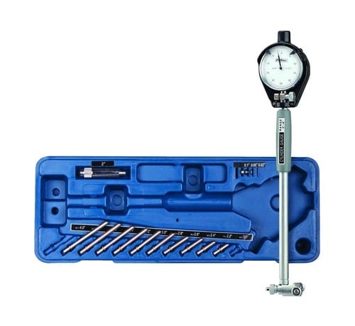
A Bore Gage is a specialized metrology tool designed to measure the internal diameter of a hole or a cylinder with extreme precision. Unlike a standard caliper, which provides an absolute measurement, a Bore Gage is typically a comparative instrument. It is engineered to detect minute deviations in size, roundness, and taper that other tools might miss.
Key Components of a Bore Gage:
-
The Measuring Head: This part enters the bore. It contains the contact points (anvils) that touch the internal walls.
-
The Stem (Extension Rod): A hollow tube that allows the head to reach deep into a cylinder while housing the transmission rod.
-
The Indicator (Dial or Digital): Mounted at the top of the stem, this unit displays the deviation from a preset reference point.
-
Centering Bridge: A spring-loaded mechanism that ensures the measuring head stays perfectly centered within the diameter of the hole.
2. Working Principle: The Art of Comparative Measurement
Radial movement of anvils converts into axial motion transmitted to dial indicator.
Centering bridges maintain alignment and prevent cosine error.
Understanding the working principle of a Bore Gage is crucial to understanding why Bore Gage Calibration is so technical. Most bore gages operate on the Comparative Principle.
2.1. Setting the Reference (The “Zero” Point)
A Bore Gage does not measure from zero; it measures from a “master” size. Before measuring a part, the gage is set using a Master Setting Ring or a high-precision outside micrometer. When the gage is inserted into this master standard, the indicator is adjusted so that it reads “0”.
2.2. Mechanical Transmission
When the gage is inserted into the actual workpiece, the contact anvils compress or expand based on the hole’s diameter. This radial movement is converted into axial movement via a precision plunger or a bell-crank mechanism inside the head. This motion travels up the stem and moves the indicator needle (or changes the digital display).
2.3. Calculating the Deviation
Calibration Formula
d = Vreading − Vstandard
Deviation = Gauge Reading − Master Standard
3. Industrial Applications: Where Accuracy is Mandatory
🚘︎
Automotive
Cylinder bores, piston holes and bearing journals inspection.
✈️
AerospaceInspection of turbine housings and landing gear components.
🛠️
Precision Bearings
Ensuring correct interference fits to prevent overheating.
The use of Bore Gages is prevalent in industries where a “close enough” measurement is unacceptable.
3.1. Automotive and Engine Rebuilding
In an internal combustion engine, the clearance between a piston and a cylinder wall is measured in ten-thousandths of an inch.
-
Application: Technicians use Bore Gages to check for cylinder wear, taper, and “ovalness” before boring or honing an engine block.
-
The Stake: Improper measurements lead to oil consumption, loss of compression, or catastrophic engine failure.
3.2. Aerospace Component Manufacturing
Aerospace parts often utilize “interference fits” where components are pressed together.
-
Application: Measuring bearing housings in turbine engines or landing gear assemblies.
-
The Stake: In aerospace, a measurement error can compromise the structural integrity of the aircraft.
3.3. Oil and Gas (Hydraulic Systems)
High-pressure hydraulic cylinders require perfectly smooth and accurately sized bores to maintain seal integrity.
-
Application: Measuring the inner walls of long hydraulic tubes.
4. Why Bore Gage Calibration is Critical
Mechanical tools are subject to physical laws. Over time, friction, temperature, and material fatigue will cause a Bore Gage to lose its accuracy.
4.1. Mechanical Wear of Anvils
Even if the anvils are tipped with carbide or hardened steel, sliding them across metal surfaces thousands of times causes microscopic wear. Bore Gage Calibration identifies this wear and determines if the anvils need replacement or adjustment.
4.2. Loss of Linearity and Hysteresis
A Gage must be accurate across its entire travel range. Linearity ensures that an error of $0.01mm$ is reported accurately whether the needle is at the beginning or the end of its stroke. Hysteresis checks if the gage returns to the same “zero” when approached from different directions.
4.3. Compliance with ISO/IEC 17025
For any facility aiming for international quality standards, traceability is a requirement. Professional Bore Gage Calibration provides a certificate that links your measurements back to national standards (NIST), proving to auditors and customers that your quality control is valid.
5. The Professional Calibration Procedure
Check cleanliness and indicator movement.
Stabilize at 20°C laboratory environment.
Use certified setting ring gauge.
Measure multiple times to calculate deviation.
6. Maintenance Best Practices
To ensure your equipment stays within tolerance between Bore Gage Calibration cycles:
-
Temperature Acclimation: Always allow the gage and the workpiece to sit in the same environment for at least 2 hours to reach thermal equilibrium (20°C is the global standard).
-
Cleanliness: Even a single speck of dust can cause an error of $0.005mm$. Clean the anvils and the bore with a lint-free cloth and isopropyl alcohol before every measurement.
-
Proper Storage: Store the gage in its original padded case to prevent the stem from bending, which would ruin the internal transmission mechanics.
Accuracy Preservation
- Avoid direct hand heat on instrument body
- Clean contacts after use
- Store inside protective case
20°C
STANDARD REFERENCE TEMP
Conclusion
The Bore Gage is a marvel of mechanical measurement, providing a window into the internal geometry of critical components. However, without regular Bore Gage Calibration, that window becomes clouded by mechanical drift and wear. By understanding the “What” and “How” of your tools and committing to professional calibration, you ensure that your manufacturing process remains precise, compliant, and world-class.
BORE GAGE CALIBRATION
Ensuring reliable measurement of internal diameters using ISO calibration procedures.
Contact usMeasured Deviation
-0.005 mm
Frequently asked questions
What is Bore Gage Calibration?
How often should a Bore Gage be calibrated?
What standards apply to Bore Gage Calibration?
What is included on the certificate?
Can you calibrate the Bore Gage on-site?
Need Bore Gage calibration?
ANAB-accredited, NIST-traceable, fast turnaround — in-lab or on-site across the USA.
Contact us for a quoteReferences & industry standards
- ISO/IEC 17025 testing & calibration laboratory requirements
- NIST calibration services and measurement traceability
- A2LA / ANAB accreditation for calibration laboratories
External standards bodies. Techmaster Electronics is an ISO/IEC 17025-accredited, NIST-traceable calibration laboratory.

Khanh Nguyen is the Marketing Manager at Techmaster Electronics, a B2B marketing leader covering the test & measurement and ISO/IEC 17025 accredited calibration industry across the US and Vietnam markets.
