
Insulation Multimeter Calibration
Accuracy across the range
How Insulation Multimeter calibration works
- Intake & visual inspection
- Environmental stabilization
- As-found measurement
- Comparison to NIST-traceable standards
- Adjustment if required
- As-left results & certificate
Your calibration, covered
In-lab vs on-site calibration
In-lab calibration
- Accredited bench with full reference standards
- Best achievable measurement uncertainties
- Pickup & return logistics handled
- Ideal for precision and reference work
On-site calibration
- We calibrate the Insulation Multimeter at your facility
- No shipping risk or transit downtime
- As-found data captured before any move
- Ideal for fixed, large or sensitive assets
In-depth guide
In the world of industrial maintenance, a multimeter that fails to provide accurate insulation resistance readings isn’t just a nuisance—it’s a severe safety liability. Imagine relying on a device that reports “Safe” while a motor winding is actually on the verge of catastrophic failure due to breakdown. This “ghost precision” leads to ignored warnings, unexpected downtime, and potential arc flash hazards that put lives at risk. The only way to bridge the gap between uncertainty and safety is through rigorous, traceable insulation multimeter calibration and maintaining a consistent calibration cycle for multimeters. This guide provides the technical blueprint for ensuring your equipment meets international standards and remains a reliable guardian of your electrical infrastructure.
Overview: The Dual Nature of Insulation Multimeters
An insulation multimeter is a hybrid instrument, combining the high-voltage generation capabilities of a megohmmeter with the precision sensing of a digital multimeter (DMM). It is used to verify the integrity of insulation in motors, cables, and switchgear by applying a known DC voltage (often up to 1000V or more) and measuring the resulting leakage current. Because these devices operate at the intersection of high resistance and high voltage, their internal components are subject to unique stresses. Over time, environmental factors and component aging can shift the measurement accuracy, making regular calibration not just a recommendation, but a regulatory necessity in fields like power generation, manufacturing, and telecommunications.The Critical Importance of Insulation Resistance Meter Error Limits
When we talk about calibration, we are essentially managing “Error.” Every instrument has a manufacturer-defined tolerance, often expressed as a percentage of the reading plus a number of least significant digits (e.g., ±(1.5% + 5)).Understanding Tolerance in High Resistance
For insulation measurements, which often reach into the Gigaohm ($G\Omega$) range, the insulation resistance meter error limits are wider than standard Ohm measurements. This is due to the extreme sensitivity required to measure nano-ampere leakage currents. A professional calibration lab will verify these limits across several voltage points (50V, 100V, 250V, 500V, and 1000V) to ensure the linearity of the internal voltage multiplier and the accuracy of the current-to-resistance conversion.The ISO/IEC 17025 Insulation Multimeter Calibration Procedure
To achieve true traceability, calibration must be performed in an ISO/IEC 17025 accredited laboratory. This standard ensures that the lab has the technical competence to produce valid results.1. Preliminary Inspection and Stabilization
Before any measurements are taken, the unit undergoes a physical inspection for battery leakage, lead integrity, and case damage. The device must be allowed to stabilize in the lab environment (typically $23^\circ \text{C} \pm 5^\circ \text{C}$) for at least 4 hours to eliminate thermal EMF errors.2. Reference Standards Selection
We use high-precision calibrators (such as the Fluke 5322A Electrical Tester Calibrator) that can simulate high resistance values while withstand voltage up to 1.1kV. These standards must have a Test Uncertainty Ratio (TUR) of at least 4:1 relative to the UUT (Unit Under Test).3. Verification of Digital Multimeter Functions
Before testing the insulation side, standard DMM functions are verified:- AC/DC Voltage: Checked against a standard voltage source.
- Low Resistance (Continuity): Verified using a 4-wire Kelvin connection to eliminate lead resistance.
- Capacitance and Frequency: Verified if applicable.
4. High Voltage Output Verification
The lab measures the actual DC voltage output of the insulation multimeter. If you set the device to 500V, the actual output must stay within a specific window (usually +10% to +20% as per safety standards like IEC 61557) to ensure the insulation is sufficiently stressed without being damaged.5. Resistance Calibration (The Core Step)
The calibrator presents a known high-resistance load to the UUT. We measure points across the entire range:- Lower Range: Checking for noise and leakage current in the $M\Omega$ range.
- Mid Range: Critical for standard industrial motor testing.
- Upper Range: Testing the limits of the $G\Omega$ range where environmental humidity can significantly impact results.
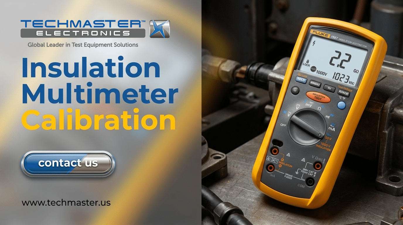
Specific Focus: Fluke 1587 Insulation Multimeter Calibration Procedure
The Fluke 1587 is the industry standard for insulation multimeters. Calibration for this specific model requires a nuanced approach due to its sophisticated filtering and “Smooth” modes.The Calibration Mode Access
To enter the calibration adjustment mode on a Fluke 1587, specific button combinations must be held during power-on (refer to the service manual for the security seal location). This allows the technician to write new constants to the EPROM based on the reference values.Key Test Points for Fluke 1587
- Insulation Functions: Verification at 50V, 100V, 250V, 500V, and 1000V. At 1000V, the resistance should be verified at $100 M\Omega$, $500 M\Omega$, and $1 G\Omega$.
- Low-Pass Filter (VFD): A unique feature of the 1587 is the filter for Variable Frequency Drives. We test this by applying a 1kHz signal and ensuring the attenuation meets the -3dB specification.
- Temperature Compensation: If using the remote probe, the thermocouple input must be calibrated separately using a dry-well or electronic simulator.
Establishing a Calibration Cycle for Multimeters
How often should you calibrate? The calibration cycle for multimeters isn’t a “one size fits all” number.- The 12-Month Standard: Most manufacturers, including Fluke and Megger, recommend a 1-year interval. This is the baseline for most ISO 9001 quality systems.
- Risk-Based Intervals: If the meter is used daily in harsh environments (high humidity, oil-mist, or high vibration), a 6-month cycle is safer.
- Stability Trends: If a device remains well within its error limits for three consecutive years, some organizations extend the cycle to 18 or 24 months, though this requires historical data justification.
Expert Advice for Maintaining Device Integrity
With two decades in the electrical testing field, I’ve seen more meters fail due to poor handling than component aging. Here are practical tips to ensure your device stays reliable between calibration intervals:- Lead Management is Key: Insulation resistance readings are only as good as the test leads. Use “Guard” terminals when available to eliminate surface leakage paths. Never use standard DMM leads for 1000V insulation tests; they lack the necessary insulation rating.
- The “Dry Box” Strategy: Store your insulation multimeter in a humidity-controlled environment. Moisture ingress into the high-impedance circuits is the #1 cause of “drifting” in the Gigaohm range.
- Battery Hygiene: Use high-quality alkaline or specified lithium batteries. Voltage drops in the battery can cause the HV inverter to work harder, generating internal heat that can temporarily shift calibration constants.
- Cleaning the Terminals: Periodically clean the input jacks with anhydrous isopropyl alcohol and a lint-free swab. Dust buildup can create a parallel resistance path, artificially lowering your insulation readings.
- Pre-Test Verification: Use a known high-value resistor (e.g., a 10MΩ 1% resistor) kept in your kit as a “check standard” to verify the meter isn’t giving wild readings before starting a major job.
FAQ
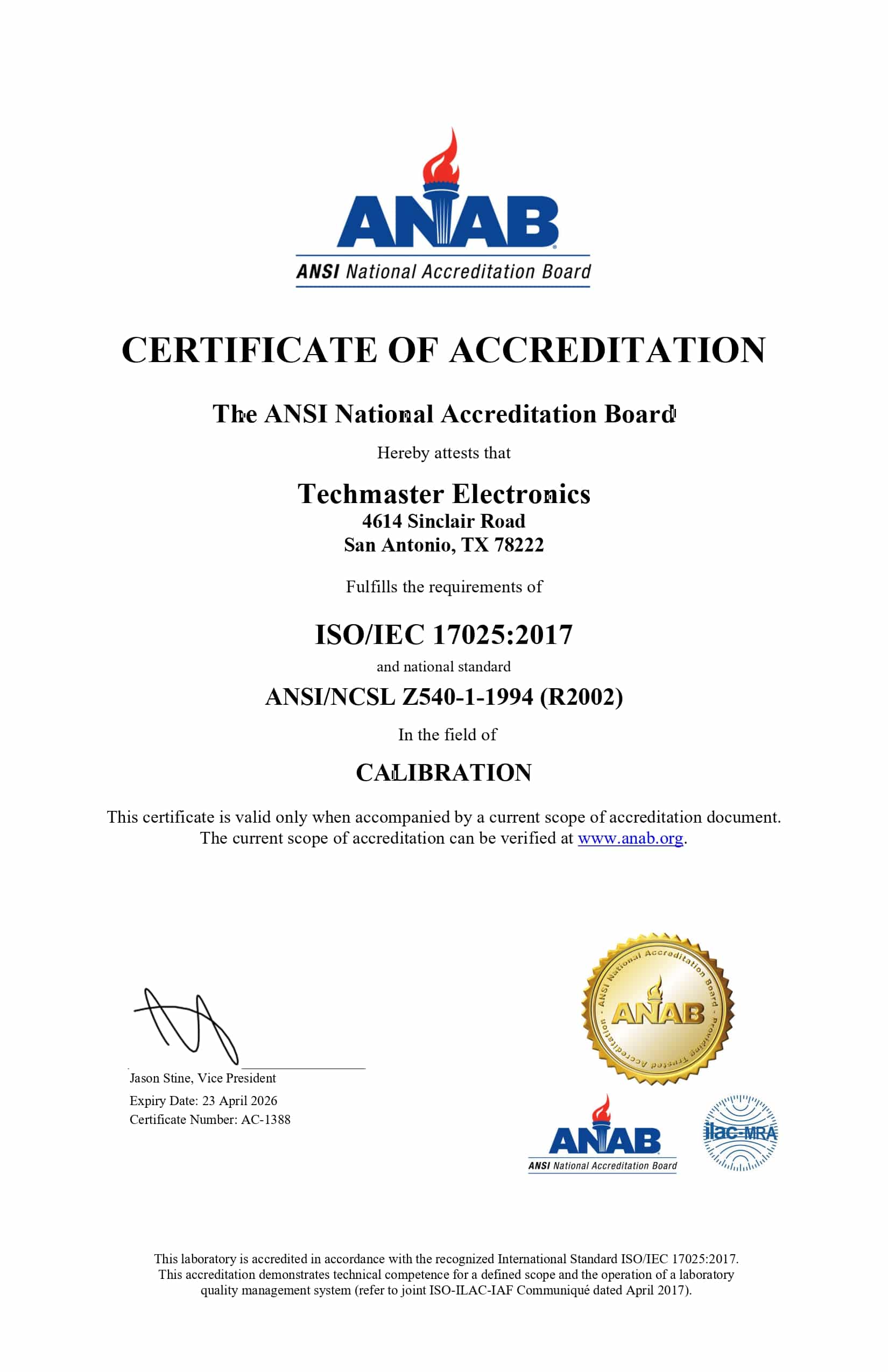
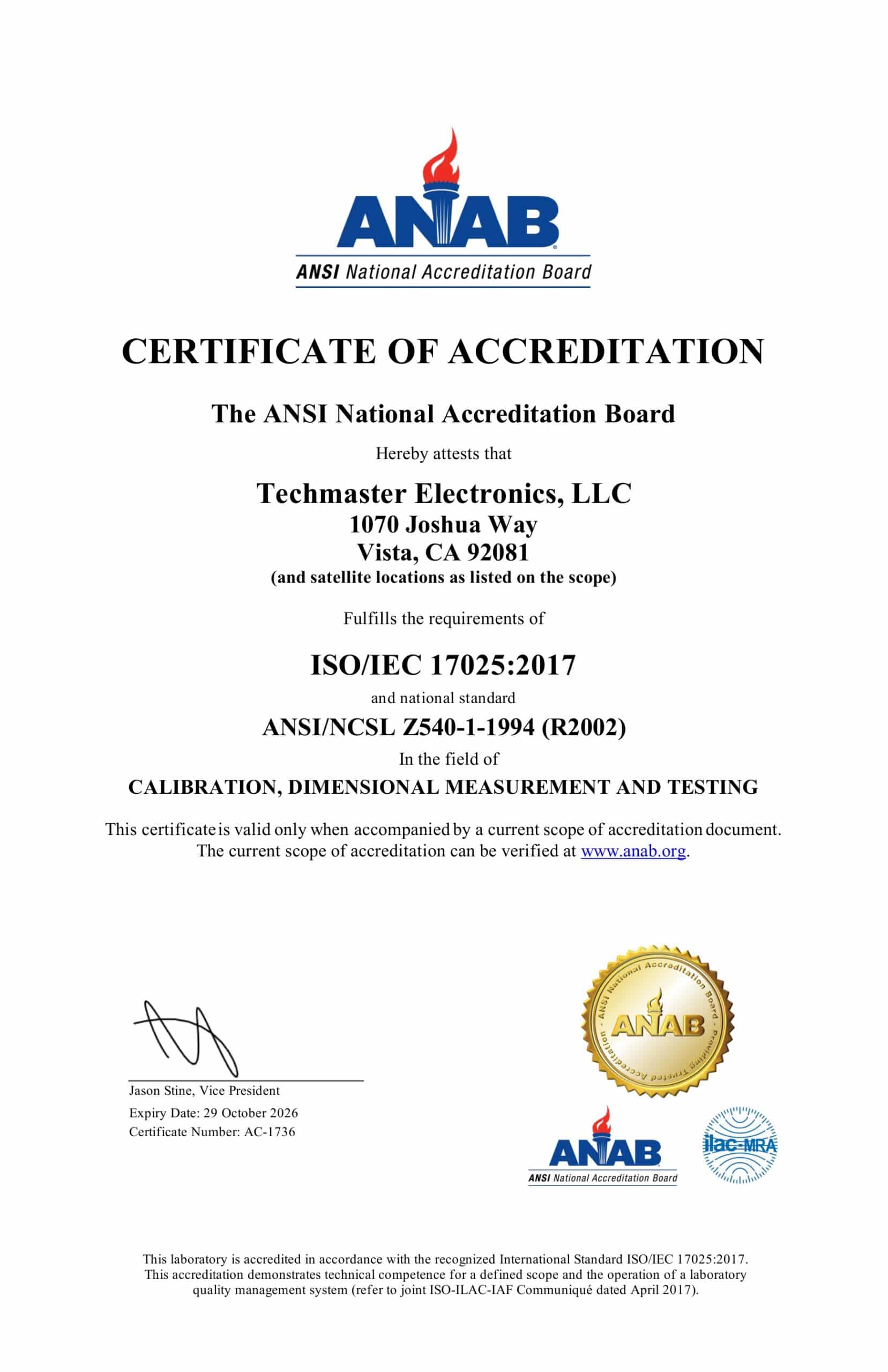
1. My meter passed DMM tests but failed Insulation tests. Why? The insulation circuit uses a high-voltage transformer and multiplier that are separate from the standard DMM voltage divider. It is common for the HV section to fail due to internal arcing or moisture while the standard Volts/Ohms remain accurate. 2. Can I calibrate my own insulation multimeter? Unless you have a high-voltage calibrator with traceable certificates and an environment-controlled lab, no. Standard resistors are not designed to handle 1000V and will break down, providing inaccurate results and potentially damaging the meter. 3. What is the difference between “Calibration” and “Adjustment”? Calibration is the act of comparing the device to a standard and recording the results. Adjustment is the act of changing the device’s internal settings to bring it back into spec. You should always receive an “As-Found” and “As-Left” report. 4. Why are the error limits so much higher for insulation (e.g., 5%) compared to DC voltage (0.09%)? Measuring extremely small currents (pico-amps/nano-amps) at high voltages is physically difficult. Small changes in air humidity or cable positioning can change the result, necessitating a wider tolerance band for meaningful measurements. 5. Does the Fluke 1587 need a special certificate? Yes, if you work in regulated industries (Aviation, Nuclear, Medical), you need a certificate that specifically states “Traceable to NIST” or your national equivalent, and ideally, an ISO 17025 accredited seal.Conclusion
In the Electrical calibration category, the insulation multimeter is one of the most vital yet complex instruments to maintain. Understanding your insulation resistance meter error limits and adhering to a strict calibration cycle for multimeters ensures that your safety data is rooted in reality, not wishful thinking. Whether you are following a Fluke 1587 calibration procedure or testing a generic megohmmeter, precision is your best defense against electrical failure. Is your equipment truly reliable? Don’t wait for a breakdown to find out. Contact our ISO/IEC 17025 accredited laboratory today to schedule your insulation multimeter calibration and ensure your team stays safe.Frequently asked questions
What is Insulation Multimeter Calibration?
How often should a Insulation Multimeter be calibrated?
What standards apply to Insulation Multimeter Calibration?
What is included on the certificate?
Can you calibrate the Insulation Multimeter on-site?
Need Insulation Multimeter calibration?
ANAB-accredited, NIST-traceable, fast turnaround — in-lab or on-site across the USA.
Contact us for a quoteReferences & industry standards
- ISO/IEC 17025 testing & calibration laboratory requirements
- NIST calibration services and measurement traceability
- NIST Time and Frequency Division
- A2LA / ANAB accreditation for calibration laboratories
External standards bodies. Techmaster Electronics is an ISO/IEC 17025-accredited, NIST-traceable calibration laboratory.

Khanh Nguyen is the Marketing Manager at Techmaster Electronics, a B2B marketing leader covering the test & measurement and ISO/IEC 17025 accredited calibration industry across the US and Vietnam markets.
