
Motor Rotation Tester Calibration
Accuracy across the range
How Motor Rotation Tester calibration works
- Intake & visual inspection
- Environmental stabilization
- As-found measurement
- Comparison to NIST-traceable standards
- Adjustment if required
- As-left results & certificate
Your calibration, covered
In-lab vs on-site calibration
In-lab calibration
- Accredited bench with full reference standards
- Best achievable measurement uncertainties
- Pickup & return logistics handled
- Ideal for precision and reference work
On-site calibration
- We calibrate the Motor Rotation Tester at your facility
- No shipping risk or transit downtime
- As-found data captured before any move
- Ideal for fixed, large or sensitive assets
In-depth guide
Motor Rotation Tester Calibration: Ensuring Safety and Efficiency in 3-Phase Systems
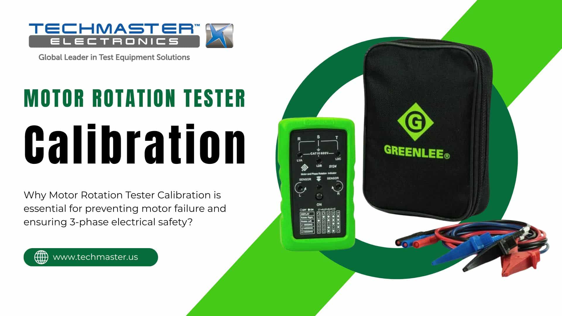
In the complex environment of industrial electrical systems, the direction of motor rotation is never a matter of preference. Instead, it is a critical factor for the survival of the machinery. If a technician connects a three-phase motor with the wrong phase sequence, the error often leads to catastrophic mechanical failure, destroyed pumps, and compromised safety. Therefore, the Motor Rotation Tester (or Phase Sequence Indicator) stands as the essential diagnostic tool for preventing these disasters. However, the reliability of this tool hinges entirely on one critical process: Motor Rotation Tester Calibration.
1. What is a Motor Rotation Tester?
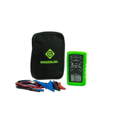
Specifically, a Motor Rotation Tester serves as a specialized handheld instrument. Professionals utilize this tool to determine the phase sequence ($L1, L2, L3$) of three-phase power supplies and the intended direction of rotation for motors. Consequently, it functions as a dual-purpose device during the installation, commissioning, and maintenance of industrial infrastructure.
Key Components
-
Input Leads: These color-coded cables connect the device directly to the power source.
-
Indicator Display: Modern units feature LED lights or digital LCD screens that clearly show “Clockwise” or “Counter-Clockwise” results.
-
Magnetic Sensors: In addition, many testers include internal sensors for non-contact testing. These sensors detect the magnetic field orientation of a running or manually turned motor.
2. Working Principles: The Science of Phase Shift
System Gatekeeper Device
In a three-phase electrical system, the ideal phase shift is:To understand the necessity of Motor Rotation Tester Calibration, one must first understand the physics behind the measurement.
2.1. The Three-Phase Principle
A three-phase electrical system consists of three alternating currents of the same frequency but reaching their peak values at different times. These phases are offset by exactly 120°.
2.2. Contact Testing (Dynamic)
When connected to a live power source, the tester analyzes the sequence in which the voltage peaks across the three leads. If the sequence is L1-L2-L3, the indicator shows a clockwise rotation. If two leads are swapped (L1-L3-L2), the sequence is reversed.
2.3. Non-Contact Testing (Static/Magnetic)
For unpowered motors, the tester utilizes internal Hall-effect sensors to detect the residual magnetism in the motor’s rotor as it is turned by hand. The tester interprets these magnetic pulses to predict which direction the motor will turn once power is applied.
3. Industrial Applications: Where Precision is Mandatory
The use of a Motor Rotation Tester is a standard operating procedure in several high-stakes sectors:
3.1. HVAC and Industrial Pumping
Centrifugal pumps and HVAC fans are designed to move fluids or air in a specific direction.
-
The Risk: Running a pump backward, even for a few seconds, can cause the impeller to unscrew from the shaft, leading to internal cavitation and total pump destruction.
-
The Solution: A calibrated tester ensures the leads are matched perfectly to the motor terminals before the first “Start” command.
3.2. Conveyor Systems and Automation
In automated assembly lines, motors must move in perfect synchronization. A single motor rotating in the wrong direction can cause belt jams, material collisions, and significant downtime.
3.3. Generator Integration
When switching between grid power and a backup generator, the phase sequence of both sources must be identical. If they are mismatched, switching the load could result in an explosive phase-to-phase short circuit.
4. Why Motor Rotation Tester Calibration is Critical
Like all electronic measurement tools, Motor Rotation Testers are susceptible to internal component drift and environmental wear.
4.1. Accuracy of the Voltage Threshold
Testers have a minimum voltage threshold required to “wake up” the phase detection circuit. Over time, internal resistors or capacitors can age, increasing this threshold. Motor Rotation Tester Calibration verifies that the tool can still accurately detect phases at low voltages or in unstable power conditions.
4.2. Sensor Sensitivity and Magnetism
In non-contact mode, the internal magnetic sensors must be highly sensitive. If the sensitivity drifts, the tester might give a “False Clockwise” reading or fail to detect rotation entirely on smaller, high-efficiency motors with low residual magnetism.
4.3. Personnel Safety and Compliance
A faulty tester is a dangerous liability. If a technician relies on a tester that reports an incorrect sequence, they may inadvertently create a hazardous electrical condition. Professional calibration at an ISO/IEC 17025 accredited laboratory provides a Certificate of Calibration, fulfilling legal and safety requirements (such as NFPA 70E or ISO 45001).
5. The Professional Calibration Procedure
01. Phase Simulation Create 3 AC signals with exact 120° phase shift and verify rotation direction.
04. Insulation Test Ensure safety under high voltage conditions (380V–600V).
A certified metrology lab follows a rigorous protocol to ensure the tester meets manufacturer specifications:
-
Visual and Continuity Inspection: Checking the integrity of the test leads and probes, as high-resistance leads can cause phase detection errors.
-
Phase Sequence Simulation: Using a 3-phase signal calibrator to feed a perfect $120^\circ$ offset signal into the tester to verify its “Clockwise” and “Counter-Clockwise” logic.
-
Frequency and Voltage Sweep: Testing the device across its rated frequency (e.g., $15\text{Hz}$ to $400\text{Hz}$) and voltage ranges to ensure linearity.
-
Magnetic Detection Verification: Placing the tester near a controlled magnetic field generator to confirm the non-contact sensors are operating within their specified sensitivity range.
6. Maintenance and Best Practices
To maintain the accuracy of your instrument between Motor Rotation Tester Calibration cycles:
-
Lead Care: Never wrap leads tightly around the device, as this can cause internal wire fractures.
-
Battery Management: Corroded batteries are the #1 cause of circuit failure in handheld testers. Remove batteries if the tool will not be used for more than 30 days.
-
Storage: Keep the device in a moisture-free environment. High humidity can cause leakage currents across the internal circuit board, leading to “ghost” phase readings.
Conclusion
The Motor Rotation Tester is a simple yet vital tool that stands between a successful machine startup and a million-dollar mechanical failure. However, a tester is only a reliable safeguard if it is properly maintained. Regular Motor Rotation Tester Calibration is not just a checkbox for auditors; it is an essential investment in the safety, reliability, and longevity of your industrial electrical infrastructure.
Frequently asked questions
What is Motor Rotation Tester Calibration?
How often should a Motor Rotation Tester be calibrated?
What standards apply to Motor Rotation Tester Calibration?
What is included on the certificate?
Can you calibrate the Motor Rotation Tester on-site?
Need Motor Rotation Tester calibration?
ANAB-accredited, NIST-traceable, fast turnaround — in-lab or on-site across the USA.
Contact us for a quoteReferences & industry standards
- ISO/IEC 17025 testing & calibration laboratory requirements
- NIST calibration services and measurement traceability
- A2LA / ANAB accreditation for calibration laboratories
External standards bodies. Techmaster Electronics is an ISO/IEC 17025-accredited, NIST-traceable calibration laboratory.

Khanh Nguyen is the Marketing Manager at Techmaster Electronics, a B2B marketing leader covering the test & measurement and ISO/IEC 17025 accredited calibration industry across the US and Vietnam markets.
