
TL;DR: RTD calibration compares a working RTD against a higher-accuracy reference RTD or SPRT at several points across its working range, but the number changes with three things most buyers overlook: the 2-, 3- or 4-wire configuration, the immersion depth, and self-heating from the measuring current. Get those recorded correctly and the calibration means something; get them wrong and a perfectly good RTD looks like it drifted. RTD calibration is not itemized in Techmaster’s section-6 scope summary, confirm accredited versus NIST-traceable before shipping.
What is RTD calibration?
RTD calibration is a comparison of a resistance temperature detector against a higher-accuracy reference RTD or standard platinum resistance thermometer (SPRT) at several points across its working range, performed with the same wiring configuration and immersion depth the sensor actually uses in service. The result is an as-found error table, not a pass/fail stamp.
Thermocouple and RTD requests formed a steady cluster reaching our laboratories over the last two quarters, split between labs asking for an accredited certificate and a peer laboratory asking to subcontract RTD work outside its own scope. RTDs and thermocouples are compared directly in thermocouple vs RTD; if you specifically have a thermocouple, see thermocouple calibration instead.
What does an RTD calibration actually check?
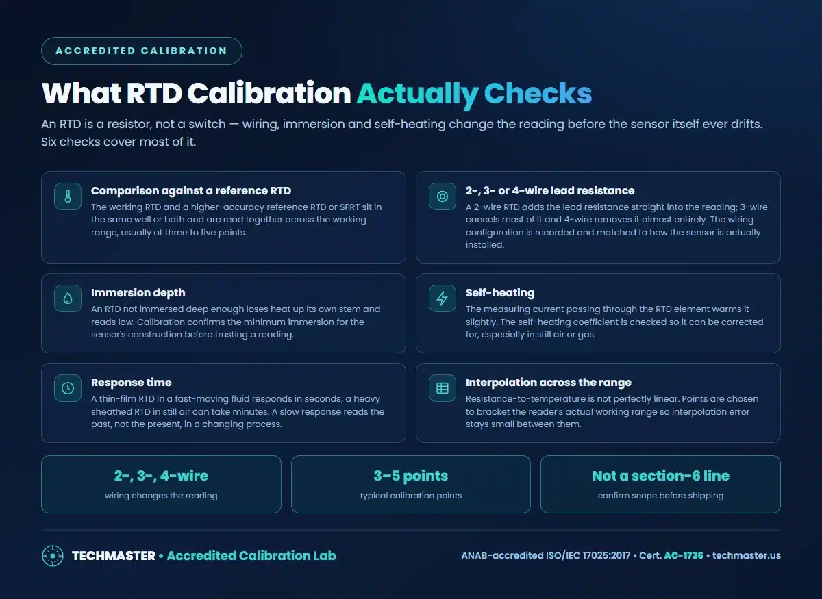
Six things: agreement with a reference RTD or SPRT at several points; the effect of 2-, 3- or 4-wire lead resistance; the sensor’s minimum immersion depth; self-heating from the measuring current; response time; and how well points chosen across the range let you interpolate between them.
Wiring and immersion are the two most common sources of an RTD looking “out of tolerance” when the sensor itself is fine, the calibration is only valid for the configuration it was performed in.
RTD or thermocouple, what changes at calibration?
| Property | RTD (e.g. Pt100) | Thermocouple |
|---|---|---|
| Sensing principle | Resistance changes with temperature | Voltage generated at a junction (Seebeck effect) |
| Wiring sensitivity | Lead resistance matters, 2-, 3- or 4-wire | Not wiring-resistance sensitive; junction and polarity matter instead |
| Typical calibration method | Comparison bath or block against a reference RTD or SPRT | Comparison against a reference, or fixed-point cells for the highest accuracy |
| Self-heating | Present, the measuring current warms the element | Not applicable; a thermocouple is a passive voltage source |
| Stability over repeated cycling | Generally more stable long-term | Junction and wire can age or contaminate faster in some types |
Why does the wiring configuration change the result?
A 2-wire measurement adds the resistance of both lead wires directly to the sensor’s own resistance, so a long or thin cable run reads high. A 3-wire configuration uses a second lead to cancel most of that error under the assumption both leads match; a 4-wire configuration drives current through one pair and measures voltage on a separate pair, removing lead resistance from the result almost entirely.
State the wiring configuration when you send an RTD for calibration, and check it against how the sensor is actually installed, a 4-wire calibration does not describe a sensor that is wired 2-wire in the field.
What capability stands behind the calibration?
RTD and thermocouple calibration is not a line item in the condensed accreditation-scope summary this rulebook works from, even though Techmaster’s laboratories already run a broad temperature-instrument program, see digital thermometer calibration, reference thermometer calibration and thermometer calibrator calibration. Ask us to confirm whether your specific RTD range and configuration are covered as accredited or supplied as NIST-traceable before you ship, the difference is explained in accredited versus NIST-traceable calibration. What a scope line actually covers is set out in calibration and measurement capability, and how to read the result in how to read an ISO/IEC 17025 certificate, with as-found and as-left data kept from every visit.
Frequently asked questions
What is the difference between calibrating an RTD and a thermocouple?
An RTD is a resistive element, so its calibration checks resistance versus temperature and is sensitive to lead-wire resistance and the wiring configuration used. A thermocouple generates its own small voltage at a junction, so its calibration compares that voltage against a reference and is more sensitive to junction condition and polarity than to wiring. The two are compared directly in thermocouple vs RTD, but they are calibrated by different methods.
How many wires does my RTD calibration need to account for?
Two, three or four, and it changes the reading. A 2-wire RTD adds the resistance of the leads straight into the measurement, which matters more on long cable runs. A 3-wire configuration cancels most of that error, and a 4-wire configuration removes it almost entirely. The calibration is recorded and reported against the wiring configuration the sensor is actually installed with, not a different one.
Why does my RTD read differently depending on how deep it is inserted?
Heat conducts up the sensor’s own stem and out through the sheath, so a shallow insertion lets the tip run cooler than the medium around it and understate the true temperature. Calibration establishes the minimum immersion depth for that sensor’s construction; using it shallower than that depth in the field will read differently than the calibration predicts, and it is not the sensor’s fault.
Is RTD calibration covered by your ISO/IEC 17025 accreditation?
Temperature and RTD calibration is not one of the capability lines summarized in this article for Techmaster’s ANAB scope, so ask us to confirm whether your RTD’s range and configuration are covered as accredited or supplied as NIST-traceable before you ship it. Send the sensor type, wiring configuration and the temperature points you need and we will check them against the current scope.
The bottom line
Tell us the sensor type, the wiring configuration you actually use, and the temperature points that matter for your process, and we will confirm the scope and return an as-found error table you can act on.
Need a quote, a rental, or a repair evaluation?
Techmaster Electronics, ISO/IEC 17025 accredited calibration laboratory, ANAB Cert. AC-1736, founded 1989. Five US labs, 5-day standard turnaround, 1–2 day expedite.
Request a quote →Techmaster Electronics, LLC is an independent ISO/IEC 17025:2017 accredited calibration laboratory. We are not affiliated with, authorized by, or endorsed by any manufacturer named on this page. All product names and model designations are trademarks of their respective owners and are used here only to identify the equipment we calibrate, repair, or rent. Confirm that our accredited scope covers your instrument’s parameters and ranges before shipping, ask us and we will check it against your model list.

Khanh Nguyen is the Marketing Manager at Techmaster Electronics, a B2B marketing leader covering the test, measurement, and ISO/IEC 17025 accredited calibration industry in the United States.