
A quality engineer at a radar or 5G test bench usually notices phase noise only after something else goes wrong: a receiver blocking test fails by 2 dB, an EVM figure drifts upward, or a Doppler target disappears into the skirt of the transmitter. The signal generator passed its last calibration, so is the generator really the problem? This guide explains how signal generator phase noise is verified, what limits the measurement, and what you should expect to see on the calibration certificate. It also covers how to check whether a phase noise result is inside or outside a laboratory’s ISO/IEC 17025 accreditation.
What is signal generator phase noise, and why does it fail tests?
IEEE Std 1139 defines L(f) as half the one-sided spectral density of phase fluctuations, Sφ(f)/2. In practice it is read as “how far below the carrier, in a 1 Hz bandwidth, is the noise at this offset.” A generator specified at −130 dBc/Hz at 10 kHz offset puts noise power 130 dB below the carrier in each hertz of bandwidth, 10 kHz away from it.
Three effects make it matter to test results:
- Reciprocal mixing. When the generator acts as an interferer or as a local oscillator, its noise sidebands mix strong adjacent signals into the receiver’s channel. Adjacent-channel selectivity and blocking tests then fail even though the receiver is healthy.
- Modulation quality. Integrated phase noise adds RMS phase error directly to EVM, so high-order QAM formats are the first to show it.
- Frequency multiplication. Phase noise rises by 20·log10(N) when a signal is multiplied by N. Doubling adds 6 dB, a ×10 multiplier adds 20 dB, and a ×40 path to millimeter-wave adds 32 dB. A source that is acceptable at 2 GHz can be the limiting factor at 77 GHz.
Phase noise is also tied to time-domain jitter. Integrating L(f) over an offset band gives RMS phase error, and dividing by 2πf0 gives RMS jitter. For example, a flat −120 dBc/Hz from 10 kHz to 1 MHz integrates to about −60 dBc, which is roughly 1.4 mrad RMS or about 224 fs of jitter on a 1 GHz carrier. For the long-term (seconds to days) side of oscillator stability, see our explainer on Allan deviation and oscillator frequency stability.
How do calibration labs measure phase noise?
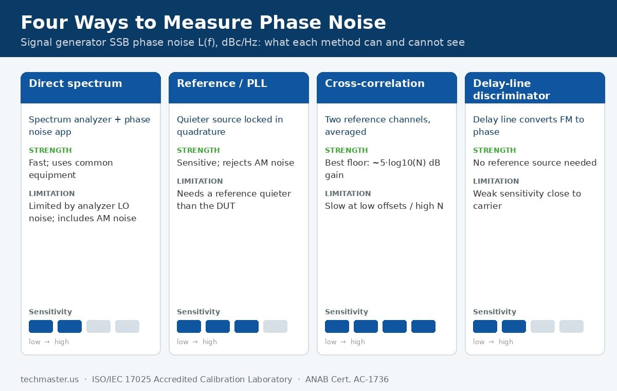
| Method | How it works | Strengths | Limitations | Typical instruments |
|---|---|---|---|---|
| Direct spectrum | Measures sideband noise power in a known resolution bandwidth and normalizes it to 1 Hz | Fast, uses equipment most labs own | Limited by the analyzer’s own LO phase noise and noise floor; AM noise is included in the reading | Spectrum and signal analyzers with a phase noise application |
| Reference source / PLL | A second source is phase-locked in quadrature and a mixer acts as the phase detector | Very sensitive and rejects AM noise | Needs a reference that is quieter than the DUT; the lock loop suppresses close-in offsets, which must be corrected | Phase noise test systems with a low-noise reference |
| Cross-correlation | Two independent reference channels measure the DUT at once; averaging the cross-spectrum cancels their uncorrelated noise | Sensitivity improves about 5·log10(N) dB with N correlations; highest dynamic range | Slow at large N for low offsets; needs care to avoid correlated spurs | Signal source analyzers such as the Keysight E5052B and Rohde & Schwarz FSWP |
| Delay-line discriminator | A delay line converts frequency fluctuation into a phase difference at the mixer | No reference source needed; good for free-running or drifting sources | Poor sensitivity close to the carrier | Discriminator test sets and analyzer options |
For a routine performance check of a lab-grade generator, the direct spectrum method is common when the analyzer is clearly quieter than the specification being tested. For low-noise sources such as the Keysight PSG family or the Rohde & Schwarz SMA100B, the analyzer’s own phase noise can be as good as or worse than the generator. In that case only a reference-source or cross-correlation system gives a defensible result. These are the same analyzers covered in our spectrum analyzer calibration guide, and their own phase noise has to be verified first.
How much better must the test system be than the generator?
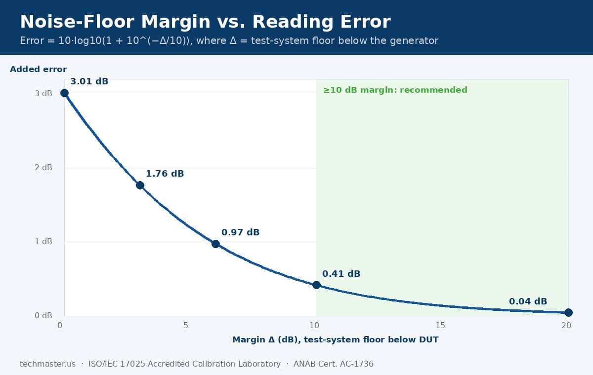
Uncorrelated noise powers add, so the measured value is the generator’s noise plus the system’s noise. The error caused by the measurement floor is 10·log10(1 + 10−Δ/10), where Δ is the margin in dB:
| Margin: test-system floor below DUT | Added reading error | What it means in practice |
|---|---|---|
| 0 dB | +3.01 dB | You are measuring the analyzer, not the generator |
| 3 dB | +1.76 dB | Not usable for a pass/fail decision |
| 6 dB | +0.97 dB | Marginal; any correction must be stated and its uncertainty included |
| 10 dB | +0.41 dB | Common rule-of-thumb minimum |
| 15 dB | +0.14 dB | Comfortable |
| 20 dB | +0.04 dB | Floor contribution is negligible |
This is the phase noise version of the test uncertainty ratio problem. A generator that is 1 dB inside its specification can be reported as failing if the floor is only 3 dB below it. The ILAC G8:09/2019 guidance on decision rules is what governs how a laboratory should handle results that sit near a limit. Our explainer on test uncertainty ratio and decision rules in calibration walks through guard banding with worked numbers.
Which carriers and offsets should be checked?
Different offset regions reveal different faults:
- Close-in (100 Hz to 1 kHz): set mostly by the internal or external 10 MHz reference. A noisy external reference degrades this region straight away.
- Loop bandwidth region (around 10 kHz to 100 kHz): where the synthesizer’s PLL design dominates. A bump here often points to a PLL or YIG-tuned oscillator problem.
- Far-out (1 MHz and beyond): set by the output chain and broadband floor. This matters most for blocking and adjacent-channel tests.
Ask for the test carriers to match your use. If your production test runs a 28 GHz 5G FR2 interferer, a certificate that only shows phase noise at 1 GHz does not support that use. The same principle applies to every parameter, as covered in our signal generator calibration guide: level accuracy, modulation and spectral purity are only verified where they were actually measured.
What should a phase noise result look like on the calibration certificate?
Check five items when you review a certificate:
- Coverage. Are the carriers and offsets you rely on listed, or only one carrier?
- As-found and as-left data. Phase noise is rarely “adjusted”, but a repair to a reference oscillator or synthesizer module changes it. The as-found data is what an impact assessment needs.
- Uncertainty. Phase noise uncertainty is usually stated in dB. Compare it with the gap between the reading and the limit.
- Decision rule. Simple acceptance, or guarded acceptance per ILAC G8?
- Accreditation status of the parameter. This is where many certificates are less complete than they look.
The last point deserves attention. Under ISO/IEC 17025:2017, an accredited laboratory can only issue accredited results for parameters and ranges listed on its scope of accreditation. Many RF scopes list absolute power, attenuation, and AM/FM/PM modulation, but do not list single-sideband phase noise as a separate line. Note that “PM” on a scope means phase modulation, not phase noise. For example, the RF/microwave lines on Techmaster’s ANAB scope (certificate AC-1736) cover RF power to 50 GHz, attenuation, AM/FM/PM, digital modulation (EVM) and noise figure. If phase noise matters to your audits, ask any laboratory, including us, whether its phase noise results are reported inside or outside its accreditation. Then read the scope document itself, as described in how CMC and accreditation scope work.
When does phase noise degrade between calibrations?
A practical between-calibration check is to compare the generator’s phase noise plot against a reference plot saved at calibration time, using the same analyzer, carrier and settings. A change of several dB in one offset region points to the cause: close-in for the reference, the loop region for the synthesizer, far-out for the output chain. Switching the generator between its internal and external reference is a quick way to see whether a lab-wide 10 MHz distribution system is the source.
Across Techmaster’s ten-year record of 381,916 calibrations, RF and microwave work accounts for 21,307 calibrations across 3,205 distinct instrument lines. Signal sources are a core part of that RF work, which is why phase noise questions come up so often during certificate reviews. The methods behind traceable oscillator measurement are documented in NIST Technical Note 1337, Characterization of Clocks and Oscillators. It remains the standard reference for phase noise and frequency-stability measurement.
Key takeaways
- Signal generator phase noise is specified as SSB L(f) in dBc/Hz at stated offsets, and it rises 20·log10(N) when the signal is multiplied by N.
- The test system’s floor should be at least 10 dB below the generator. At 3 dB margin, a good generator reads 1.76 dB worse than it really is.
- Check the carriers and offsets you actually use. One carrier at 1 GHz does not verify performance at 28 GHz.
- A complete certificate shows carrier, offset, L(f), limit, uncertainty, decision rule and accreditation status.
- “PM” on an accreditation scope means phase modulation, not phase noise. Confirm whether phase noise results are accredited.
Frequently asked questions
Is phase noise part of a standard signal generator calibration?
It depends on the procedure. Many manufacturer performance-verification procedures include SSB phase noise at specified offsets, but some abbreviated calibrations check only frequency, level and modulation. Ask the laboratory which offsets and carriers are tested and whether the results appear on the certificate.
Can a spectrum analyzer measure signal generator phase noise accurately?
Yes, if the analyzer’s own phase noise is at least 10 dB below the generator at each offset. For low-noise generators, a general-purpose analyzer often cannot meet that margin, and a reference-source or cross-correlation phase noise analyzer is needed.
Does phase noise drift like frequency accuracy does?
Not usually. Frequency accuracy drifts gradually with reference oscillator aging, while phase noise tends to stay stable until a component fails or is repaired. That is why a saved reference plot is a useful between-calibration check.
Why does my generator meet phase noise spec at 1 GHz but fail at 20 GHz?
Phase noise rises by 20·log10(N) when frequency is multiplied by N, so 20 GHz carries about 26 dB more phase noise than 1 GHz from the same reference. Datasheet limits are stated per band, so each band needs its own check.
What does PM on an accreditation scope mean?
PM means phase modulation, for example phase deviation in radians. It is a different parameter from single-sideband phase noise in dBc/Hz. Check the scope for a separate phase noise line if you need accredited phase noise results.
How often should signal generator phase noise be verified?
Verify it at each scheduled calibration, typically every 12 months, and again after any repair to the reference or synthesizer, after shipping damage, or whenever receiver blocking or EVM results change without explanation.
Need your RF sources verified where you use them? Techmaster Electronics, founded in 1989, holds ISO/IEC 17025:2017 accreditation from ANAB (certificate AC-1736) at four US laboratories: Vista and Santa Clara, CA, Orlando, FL and San Antonio, TX. See our ISO/IEC 17025 RF and microwave calibration services or the full range of accredited calibration services, then request a quote for signal generator calibration and tell us which carriers and offsets you need on the certificate.

Khanh Nguyen is the Marketing Manager at Techmaster Electronics, a B2B marketing leader covering the test, measurement, and ISO/IEC 17025 accredited calibration industry in the United States.