

TL;DR
Rogowski coil calibration verifies the coil and its integrator together as one system, at several currents and frequencies, with the conductor deliberately moved inside the loop. Most coils drift because the integrator gain ages and the closure latch wears, not because the winding changes. Expect 0.5–2 % total.
What is a Rogowski coil, and why can it not measure DC?
That single physical fact drives everything about how the device is used and how it must be calibrated. There is no iron core, so there is nothing to saturate, a coil rated for 3,000 A behaves exactly the same at 30 A and at 30,000 A of fault current. There is also almost no insertion burden: the coil takes negligible energy from the circuit, which is why power-electronics engineers reach for one when they need to instrument a busbar without breaking it.
The trade-off is that the sensing element on its own is useless. The raw coil output is a small di/dt voltage; the amplitude scaling, the low-frequency roll-off and the DC-offset behaviour all live in the integrator box at the end of the cable. The coil and the integrator are a matched pair, and calibrating one without the other proves nothing. Any calibration certificate that lists only a coil serial number, with no integrator serial number, is describing an incomplete measurement system.
Internationally, flexible and rigid Rogowski-type sensors with an analogue output fall under the low-power passive current transformer family described in IEC 61869-10:2017, which applies to devices with a rated frequency from 15 Hz to 100 Hz. That standard is the reason most manufacturer accuracy classes are quoted at 50 Hz or 60 Hz, and the reason a coil used for switching-converter work at 20 kHz is operating well outside its rated specification unless the supplier has characterised it there.
Why does a Rogowski coil drift out of tolerance between calibrations?
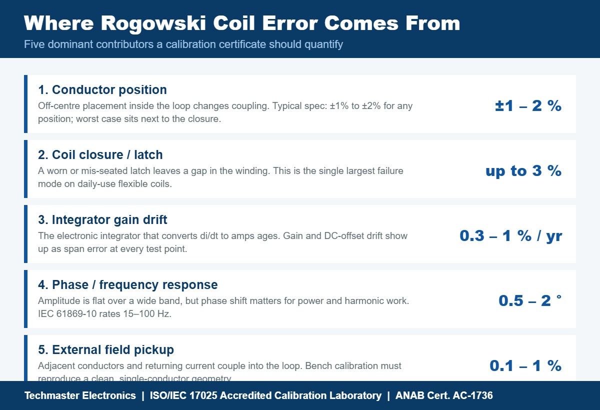
In a decade of records from Techmaster’s laboratories, 381,916 calibrations across 4,913 manufacturers, the pattern for clamp-on AC current sensors is consistent: out-of-tolerance findings cluster in the electronics and the mechanics, not in the sensing element itself. A copper helix on a flexible former is remarkably stable, so a flexible AC current probe almost always fails at its electronics or its latch. A latching plastic closure that has been snapped shut around a live busbar 400 times in a year is not.
Integrator gain and offset drift
The integrator is an analogue circuit, typically an op-amp with a feedback capacitor, or a digital equivalent sampling the coil output. Its gain-setting resistors and reference age. A 0.3 % to 1 % annual gain shift is unremarkable and completely invisible to the operator, because the reading still looks plausible. This is exactly the failure mode that an ISO/IEC 17025 measurement uncertainty budget is designed to expose: the error is systematic, repeatable, and therefore correctable, but only if someone measures it.
Closure and latch wear
A flexible coil relies on the two ends meeting cleanly so the winding is electrically continuous around the loop. A worn latch leaves a small gap, and the coil’s sensitivity in the region of that gap changes. Because the gap is at a fixed point on the loop, the resulting error depends on where the conductor sits relative to it, which is why an accurate calibration must include a deliberate worst-case position test, not just a centred one.
Cable and connector damage
The lead between coil and integrator carries a low-level signal. Crushed cable, corroded shells and intermittent shield connections raise noise and can introduce a small, load-dependent attenuation. On bench calibration this shows as poor repeatability rather than a clean offset, a useful diagnostic distinction.
How much error does conductor position inside the loop really add?
Theory says a perfect Rogowski coil with a uniform, constant turns-per-unit-length winding is completely insensitive to conductor position, Ampère’s circuital law does not care where inside the loop the current flows. Practice says the winding is never perfectly uniform, and the closure is a discontinuity by construction.
For a quality manager, this has a blunt implication: a certificate that only records a centred-conductor result understates the error a technician will see in the field. When Techmaster calibrates a flexible coil, the test sequence includes a centred position, an off-centre position near the far side of the loop, and a position adjacent to the closure, because that is how the instrument is actually used on a crowded switchboard where the operator takes whatever geometry the cable allows.
Practical tip for field use: mark the coil with a permanent orientation arrow after calibration and train technicians to keep the closure away from the conductor. It costs nothing and removes the largest single field error contributor.
How is a Rogowski coil calibrated in an accredited laboratory?
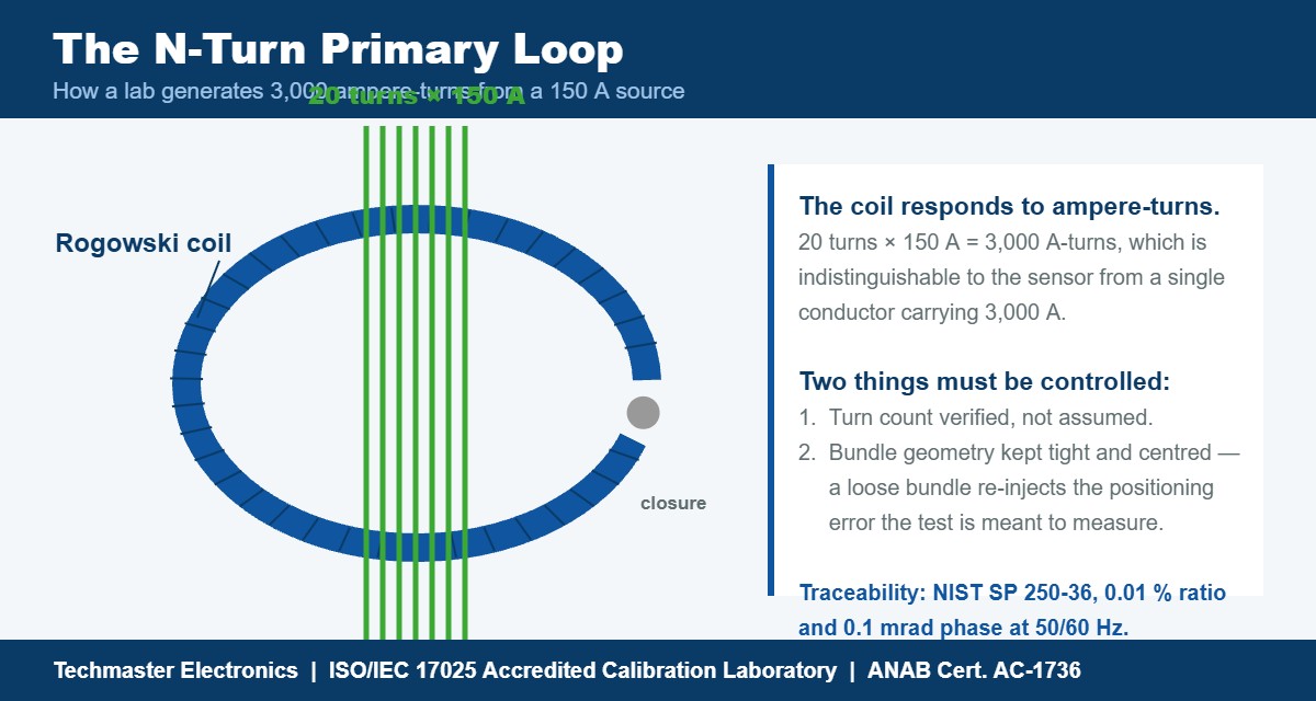
The reference chain matters. Traceability for AC current in the United States runs back to NIST, which calibrates reference current transformers at 50 Hz, 60 Hz and 400 Hz with expanded uncertainties of about 0.01 % in ratio and 0.1 mrad in phase angle at power frequencies, as documented in NIST Special Publication 250-36. A laboratory’s working standards inherit from that chain, and the resulting calibration and measurement capability (CMC) is what appears on the accreditation scope.
The N-turn coil trick
Generating 3,000 A in a laboratory is expensive and thermally brutal. Instead, the primary conductor is looped through the Rogowski coil N times. Twenty turns carrying 150 A presents 3,000 ampere-turns to the sensor, indistinguishable, to the coil, from a single conductor carrying 3,000 A. The turn count must be verified and the geometry controlled, because a sloppy multi-turn bundle reintroduces the positioning error the test is trying to characterise.
| Test point | Current | Frequency | Conductor position | What it proves |
|---|---|---|---|---|
| Zero / noise floor | 0 A | , | Centred | Integrator offset and noise |
| Low span | 10 % of range | 60 Hz | Centred | Resolution and low-end linearity |
| Mid span | 50 % of range | 60 Hz | Centred | Nominal gain accuracy |
| Full span | 100 % of range | 60 Hz | Centred | Top-of-range linearity |
| Position, far side | 50 % of range | 60 Hz | Off-centre, opposite closure | Winding uniformity |
| Position, worst case | 50 % of range | 60 Hz | Adjacent to closure | Latch integrity (worst case) |
| Frequency, low | 50 % of range | 50 Hz | Centred | IEC 61869-10 rated band, low end |
| Frequency, high | 50 % of range | 400 Hz | Centred | Aerospace / 400 Hz bus use |
| Phase angle | 50 % of range | 60 Hz | Centred | Power and harmonic measurement validity |
Phase angle deserves special attention. If the coil is only ever used to read RMS amps, a degree or two of phase shift is irrelevant. If it feeds a power analyser computing real power or power factor, phase error translates directly into watt error, and at a power factor of 0.5, a 1° phase error produces roughly a 3 % error in indicated real power. Tell your calibration provider which application applies, because it changes what has to be reported.
Rogowski coil, clamp CT or shunt, which sensor should you calibrate?
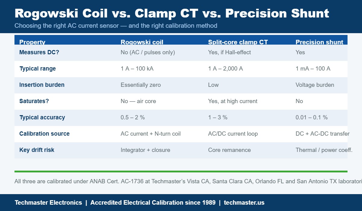
Each sensor type demands a different reference setup, which is why they carry different uncertainties on an accreditation scope. Shunts are calibrated by DC resistance measurement plus an AC-DC difference transfer; NIST performs broadband AC-DC difference calibrations of current shunts from 3 A to 100 A at frequencies up to 30 kHz. Clamp CTs need a current loop that can deliver both AC and DC, and Hall-effect types need a degauss step before every reading because core remanence produces a stubborn zero offset. Rogowski coils need a clean, controlled geometry above all else.
If your bench mixes all three, read our companion guides on clamp meter calibration for electrical safety compliance and current transducer calibration for precision power monitoring, both of which sit within Techmaster’s ISO/IEC 17025 accredited electrical calibration discipline.
How often should a Rogowski coil be calibrated?
ISO/IEC 17025:2017 does not prescribe intervals. ILAC G24:2022, the international guidance on determining recalibration intervals, sets out the recognised methods, automatic staircase adjustment, control-chart analysis, and in-use time, and expects the interval to be reviewed against evidence rather than fixed by habit.
For a flexible AC current probe specifically, two site factors dominate the recalibration interval decision:
- Cycle count on the closure. A coil used for routine energy audits may be opened and closed dozens of times a day. Latch wear is a mechanical fatigue process; a calendar interval does not track it well. Consider counting cycles or scheduling by job count.
- Consequence of an undetected error. If the coil supports arc-flash studies, utility revenue metering, or product qualification testing, the cost of a silent 2 % error is far higher than the cost of a shorter interval.
Between calibrations, a simple intermediate check restores confidence cheaply: pass a known current from a stable source through a fixed N-turn fixture and record the reading on a control chart. A trend is a warning; a step is a failure.
Where can you get accredited Rogowski coil calibration in the United States?
Flexible AC current probe calibration, Rogowski coils, current transducers, clamp meters and precision shunts alike, is handled within the electrical discipline. Because the coil and integrator must travel together, ship both, plus any adapter cables you rely on in service, so the certificate describes the system you actually use.
Techmaster’s accredited electrical scope, alongside the other calibration disciplines on the AC-1736 scope, is published on the ANAB Cert. AC-1736 accreditation page. Accreditation status can also be verified independently through the ANSI National Accreditation Board directory. Full addresses and hours for every site are listed on the Techmaster US laboratory and office locations page. Free local pickup and delivery is available in Silicon Valley, Southern California and Orlando, and standard turnaround is five business days.
Key takeaways
- A Rogowski coil measures di/dt, so it cannot read DC, and the integrator, not the winding, sets the accuracy.
- Calibrate the coil and its integrator as one matched system; a certificate without the integrator serial number is incomplete.
- Integrator gain drift (0.3–1 % per year) and closure-latch wear are the dominant out-of-tolerance causes.
- Conductor position must be tested at worst case, adjacent to the closure, not just centred.
- Use an N-turn primary loop to synthesise high ampere-turns; verify turn count and control the geometry.
- Report phase angle if the coil feeds a power analyser: 1° of phase error is roughly 3 % of real power at 0.5 PF.
- Set intervals from evidence using ILAC G24:2022 methods, and weight the decision by closure cycle count.
- Accredited current probe calibration to ISO/IEC 17025 must state the current and frequency points covered by the CMC.
Frequently asked questions about Rogowski coil calibration
Can a Rogowski coil measure DC current at all?
No. A Rogowski coil responds to the rate of change of current, and a steady DC current has no rate of change, so the output is zero. If you need DC capability in a clamp-on form factor, you need a Hall-effect or fluxgate split-core probe instead. Some hybrid probes combine a Hall sensor for DC with a Rogowski or transformer path for AC, and those must be calibrated on both paths.
Does the Rogowski coil integrator need to be calibrated separately?
It should not be. The coil and integrator form a single measuring system whose combined transfer function determines the reading in amps. Accredited practice is to calibrate them together, with both serial numbers recorded on the certificate. If the integrator is later swapped for another unit, the system calibration is void and must be repeated.
What accuracy can I realistically expect from a Rogowski coil?
Typical flexible Rogowski coils are specified at 0.5 % to 2 % of reading including positioning effects, at power frequency. Rigid, precision-wound coils can do better. If you need 0.1 % or tighter, a precision shunt with an AC-DC transfer calibration is the correct instrument, not a Rogowski coil.
Why does my Rogowski coil read differently depending on where the cable sits?
Because the winding is not perfectly uniform and the closure joint is a discontinuity. Error is normally largest with the conductor pressed against the closure. Marking an orientation on the coil and training technicians to keep the closure away from the conductor removes most of this variation in day-to-day use.
How long does accredited Rogowski coil calibration take at Techmaster?
Standard turnaround is five business days from receipt. Expedited one to two business day service is available on many units for a nominal fee. Contact your account manager or email sales@techmaster.us to arrange expedited handling before shipping.
Is Rogowski coil calibration covered by Techmaster’s ISO/IEC 17025 accreditation?
Electrical calibration is on Techmaster’s ANAB scope under Cert. AC-1736 at the Vista CA, Santa Clara CA, Orlando FL and San Antonio TX laboratories. Because accreditation scopes are defined by measurement parameter and range rather than by instrument name, confirm the specific current and frequency points you need when you request a quote, and the laboratory will state whether they fall inside the accredited CMC.
Need a Rogowski coil calibrated to ISO/IEC 17025?
Send us the coil, the integrator and the current and frequency points you need. We will confirm accredited coverage before the unit ships.
Request a Calibration Quote
Khanh Nguyen is the Marketing Manager at Techmaster Electronics, a B2B marketing leader covering the test, measurement, and ISO/IEC 17025 accredited calibration industry across the US and Vietnam markets.