
A biomedical technician replaces the power supply board in an infusion pump, runs the post-repair electrical safety test, and gets an equipment leakage reading of 410 µA on a Class I device. Is that a pass? Under the IEC 62353 direct method the limit is 500 µA, so yes. A colleague who learned on IEC 60601-1 tables argues it is nowhere near the 100 µA touch-current figure and wants the pump pulled. Both are quoting real numbers. They are quoting numbers from two standards written for two different jobs, and the debate gets worse if nobody can say how accurate the safety analyzer itself was at 410 µA.
This guide settles the IEC 62353 vs IEC 60601-1 question for clinical engineering managers, biomed technicians, medical device quality engineers and the metrology coordinators who keep their test equipment in calibration. It explains which standard governs which test, compares the published limits in one table, shows why the two methods give different readings on the same device, places NFPA 99 and the FDA Quality Management System Regulation in the US picture, and then turns to the part most articles skip: what an electrical safety analyzer calibration has to prove for any of those limits to mean anything. The guidance comes from Techmaster Electronics, founded in 1989 and accredited to ISO/IEC 17025 by ANAB (Certificate AC-1736), which calibrates safety analyzers at its four accredited laboratories in Vista and Santa Clara, California, Orlando, Florida, and San Antonio, Texas.
What is the difference between IEC 62353 and IEC 60601-1?
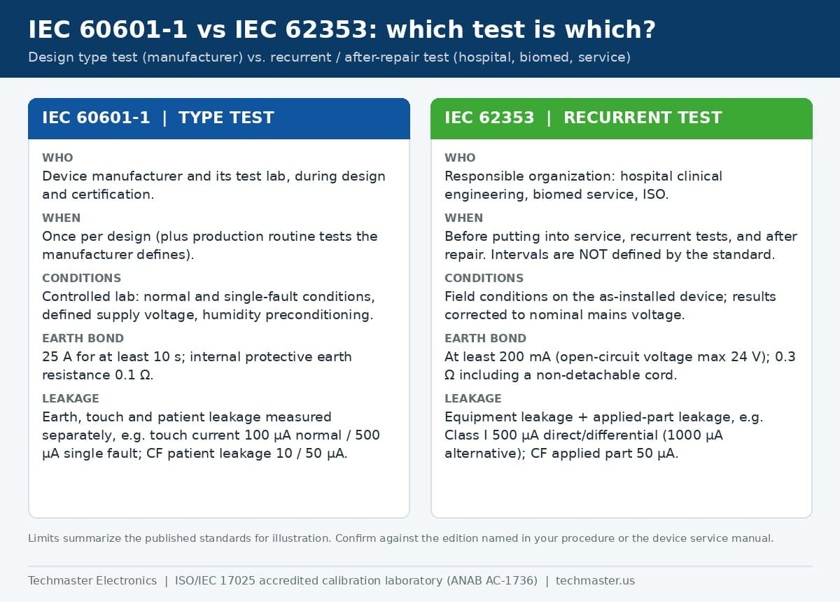
IEC 60601-1 (“Medical electrical equipment – Part 1: General requirements for basic safety and essential performance”) is a design standard. A manufacturer, usually with a certification lab, proves that a model is safe under normal condition and under single-fault conditions such as an open protective earth or a reversed supply. The tests are thorough and partly destructive: humidity preconditioning, supply voltage set to 110 % of rated, a high-current protective earth bond test (25 A, or 1.5 times rated current if greater) against a 0.1 Ω limit, or 0.2 Ω including a non-detachable power cord, and separate measurements of earth leakage, touch current and patient leakage.
IEC 62353:2014, Medical electrical equipment – Recurrent test and test after repair of medical electrical equipment, exists because those type tests are neither practical nor safe to repeat on a device that is already in a patient-care area. It defines tests a responsible organization can perform on installed equipment with a portable safety analyzer, and it states plainly that it does not set the time intervals for recurrent tests; the interval is your decision, informed by the manufacturer’s documentation and your equipment management program.
Put simply: IEC 60601-1 answers “was this model designed safely?” IEC 62353 answers “is this particular unit still safe today, after transport, wear and repair?”
Which standard applies to your test: type test, acceptance, recurrent or after repair?
- Design verification and certification. IEC 60601-1 and its collateral and particular standards (for example IEC 60601-2-24 for infusion pumps). This is the manufacturer’s responsibility.
- Production-line testing. The manufacturer defines routine tests in its own quality system, normally a reduced set derived from the type tests: earth bond, dielectric strength with a calibrated hipot tester for dielectric withstand and leakage current, and selected leakage measurements.
- Acceptance before putting into service. IEC 62353 defines “putting into service” as the first use after setting up at the responsible organization. Its test establishes the baseline that later recurrent results are trended against.
- Recurrent (preventive maintenance) tests. IEC 62353, at the interval your program sets.
- After repair. IEC 62353, plus any function checks the service manual requires. The logic is the same as for test equipment: a repair breaks the link to the last good result, which is why calibration after repair with as-found data matters for your analyzer too.
The most common mistake we see is not choosing the wrong standard; it is mixing them, for example running an IEC 62353 alternative-method measurement and then judging it against an IEC 60601-1 touch-current limit. Pick one method per test, record it on the test record, and apply that method’s limit.
How do IEC 62353 vs IEC 60601-1 limits compare side by side?
| Measurement | IEC 60601-1 (type test) | IEC 62353 (recurrent / after repair) |
|---|---|---|
| Protective earth resistance | 0.1 Ω without cord; 0.2 Ω including a non-detachable cord; 25 A (or 1.5× rated current) test | 0.3 Ω with non-detachable cord; detachable cord: 0.2 Ω equipment + 0.1 Ω cord (0.3 Ω together); at least 200 mA, open-circuit voltage up to 24 V |
| Earth leakage | 5 mA normal / 10 mA single fault | Not measured separately (covered by equipment leakage) |
| Touch (enclosure) current | 100 µA normal / 500 µA single fault | Covered by equipment leakage |
| Equipment leakage, Class I | — | 500 µA direct or differential; 1,000 µA alternative method |
| Equipment leakage, Class II | — | 100 µA direct or differential; 500 µA alternative method |
| Patient leakage, Type B / BF | 100 µA normal / 500 µA single fault (AC) | BF applied-part leakage (mains on applied part): 5,000 µA; Type B not measured |
| Patient leakage, Type CF | 10 µA normal / 50 µA single fault (AC) | CF applied-part leakage: 50 µA |
| Insulation resistance | Dielectric strength test instead | Optional; measured at 500 V DC |
Values summarize IEC 60601-1 (3rd edition) and IEC 62353:2014 as published and as reproduced in safety-analyzer manufacturer guides. Always confirm against the edition named in your procedure or in the device service manual, and against any particular standard for the device type.
Notice what the IEC 62353 numbers are not: they are not “looser” versions of the same measurement. The equipment leakage test is performed so that it gives the same result as a single-fault condition, which is why its Class I limit (500 µA) matches the IEC 60601-1 single-fault touch-current limit rather than the 100 µA normal-condition figure. In the opening example, 410 µA by the direct method is a pass, but only if the analyzer’s error at that point is small enough not to matter; we come back to that below.
Why do IEC 62353 and IEC 60601-1 readings disagree on the same device?
The three IEC 62353 leakage methods
- Alternative method. Live and neutral are shorted together and a test voltage at mains frequency is applied between them and the protective earth or enclosure, with the device not connected to the mains supply. It is safe and repeatable, and because it stresses all insulation at once it tends to read higher, which is why its limits are higher. The standard requires another method if the alternative-method result exceeds 5 mA.
- Direct method. The device runs from mains and the analyzer measures current through the measuring device (MD) with the protective earth interrupted. It most closely resembles the IEC 60601-1 approach, but it momentarily removes the earth while the device is powered, so the device must be isolated from earth during the test.
- Differential method. The analyzer measures the imbalance between live and neutral current while the device runs normally. It does not interrupt the earth, but it has a resolution floor, so it is not suited to very low readings.
IEC 62353 also requires measured leakage to be corrected to the value at nominal mains voltage. If the outlet delivers 114 V and your nominal is 120 V, the analyzer scales the reading up by 120/114. That scaling relies on the analyzer’s own mains-voltage measurement, so an error there flows straight into every leakage result.
Both standards use the same measuring device network, 10 kΩ in parallel with 0.015 µF, in series with a 1 kΩ sensing resistor. The network weights leakage by frequency so that higher-frequency currents, which the body tolerates better, count for less. If the MD inside an analyzer drifts or a component fails, readings on devices with switch-mode power supplies change even when the analyzer still reads perfectly at DC.
Where do NFPA 99 and the FDA QMSR fit for US facilities and manufacturers?
For a US clinical engineering department, IEC 62353 is a method, not a legal requirement in itself. Many programs adopt it because it gives a consistent, documented way to test before service, after repair and at recurrent intervals, and because modern safety analyzers automate its sequences. What auditors look for is consistency: a written policy that names the test standard and limits per device class, test records that state the method used, and evidence that the analyzer producing the numbers is calibrated. When a manufacturer’s service manual specifies a test, follow it for that device.
For manufacturers, the FDA Quality Management System Regulation, 21 CFR Part 820, became effective on February 2, 2026, and incorporates ISO 13485:2016 by reference. ISO 13485 clause 7.6 requires monitoring and measuring equipment to be calibrated or verified against standards traceable to international or national measurement standards, which covers the safety analyzers and hipot testers on a production line. Our guide to biomedical test equipment calibration for hospitals and device makers covers the wider set of analyzers in that program.
What must an electrical safety analyzer calibration cover?
Analyzers such as the Fluke Biomedical ESA612 and ESA615, the Rigel 288+ and the Dale Technologies LT544D series are, inside, a precision multimeter, a low-ohm meter with a current source, a 500 V insulation tester and a frequency-weighted microammeter in one box. Each needs its own verification. In Techmaster’s 10-year calibration history of 381,916 calibrations, the three medical safety analyzer models in our top 1,000 instruments alone account for 175 calibrations, all performed in-house: 78 on the Dale LT544D Lite, 65 on the LT544D Plus and 32 on the Fluke ESA612. The functions below are the ones those certificates have to cover.
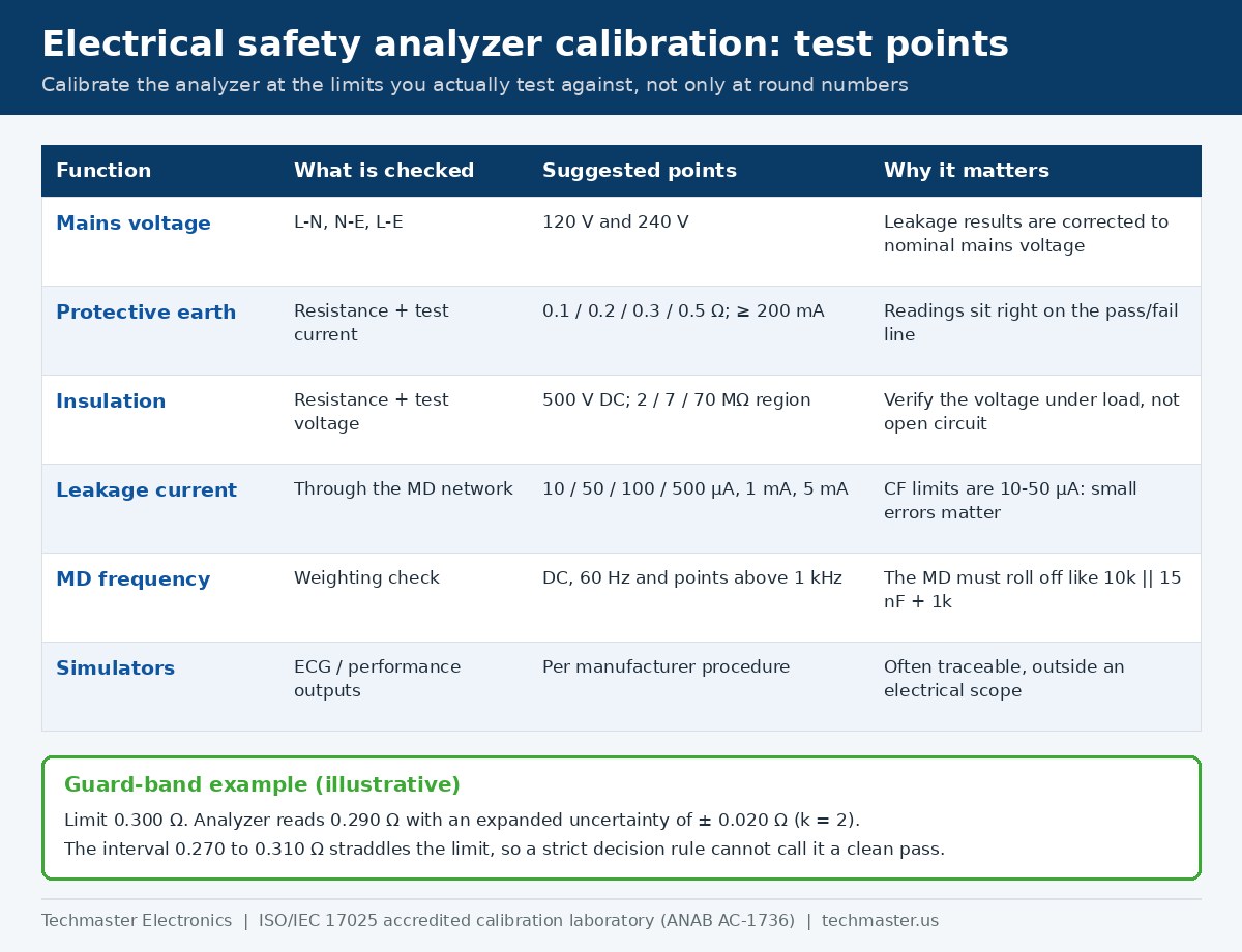
| Analyzer function | What to verify | Points worth requesting |
|---|---|---|
| Mains voltage (L–N, N–E, L–E) | Voltage reading; it drives the nominal-voltage correction | 120 V and 240 V |
| Protective earth / point-to-point resistance | Resistance reading and the actual test current delivered | 0.1, 0.2, 0.3 and 0.5 Ω, plus 1 to 2 Ω; current at least 200 mA |
| Insulation resistance | Resistance and the 500 V DC output under load | Low-MΩ points near your pass limits, plus a high decade |
| Leakage current (through the MD) | AC and DC microampere readings | 10, 50, 100 and 500 µA, 1 mA and 5 mA |
| MD frequency weighting | Response versus frequency | DC, 60 Hz and points above 1 kHz |
| ECG and performance simulation | Amplitude and rate outputs | Per the manufacturer’s procedure |
Why test points at the limits matter
Protective earth readings on healthy Class I equipment routinely land between 0.1 and 0.3 Ω, right on top of the limits. Suppose your analyzer reads 0.290 Ω against a 0.300 Ω limit and its expanded uncertainty at that point is ±0.020 Ω (k = 2). The true value could be anywhere from 0.270 to 0.310 Ω, so under a strict decision rule the result is not a clean pass. The same arithmetic applies to CF applied parts, where the limit is 50 µA and a few microamperes of analyzer error is a large fraction of the margin. Our explainer on test uncertainty ratio and decision rules in calibration shows how to set a guard band once you know the analyzer’s uncertainty at each point.
At Techmaster, the electrical measurements in safety analyzers (voltage, current and resistance) fall under the DC and low-frequency electrical field of our ANAB scope, available at all four accredited labs, as listed on our medical calibration scope for biomedical analyzers. Patient-simulator functions are not on that scope and are issued on a NIST-traceable certificate, so ask any lab to state clearly which functions its accredited certificate covers.
What should you check on the analyzer’s calibration certificate?
- As-found data first. If the analyzer was out of tolerance when it arrived, every pass or fail it issued since its last good calibration is in question. As-found data is what lets you scope that review instead of re-testing the whole fleet.
- Points that match your limits. A certificate with only 1 Ω and 10 Ω resistance points says little about performance at 0.2 or 0.3 Ω.
- Stimulus values, not just readings. Earth-bond current below 200 mA, or an insulation voltage that sags well under 500 V on load, can make a weak connection or poor insulation look acceptable.
- Uncertainty and decision rule. ISO/IEC 17025 requires the decision rule to be agreed when a statement of conformity is issued; make sure it is stated on the certificate.
- Accredited versus traceable. Compare the functions on the certificate with the lab’s scope of accreditation. The ANAB directory at anab.ansi.org lets you confirm a lab’s accreditation status.
- A defensible interval. A 12-month interval is a common starting point for safety analyzers; adjust it with as-found history, as described in our guide to setting calibration intervals with ILAC G24.
For instrument-specific detail, see our electrical safety analyzer calibration guide, or browse the full range of ISO/IEC 17025 medical equipment calibration services within our accredited calibration services hub.
Key takeaways
- IEC 60601-1 is the manufacturer’s design type test; IEC 62353 covers testing before putting into service, recurrent tests and tests after repair.
- Never judge an IEC 62353 result against an IEC 60601-1 limit, or the reverse; record the method and apply its own limit.
- IEC 62353 protective earth: 0.3 Ω including a non-detachable cord at 200 mA or more. Class I equipment leakage: 500 µA direct or differential, 1,000 µA alternative.
- US facilities also answer to NFPA 99 (0.50 Ω ground resistance); manufacturers answer to the FDA QMSR and ISO 13485 clause 7.6.
- Calibrate the safety analyzer at limit-adjacent points, verify test current, test voltage and MD frequency response, and demand as-found data.
Frequently asked questions
Can a US hospital use IEC 62353 instead of NFPA 99?
IEC 62353 is a test method standard, while NFPA 99 is the code many US health care facilities are inspected against. Many programs use IEC 62353 methods for acceptance, recurrent and after-repair tests, provided their written policy shows how those tests and limits satisfy NFPA 99, the manufacturer’s instructions and the facility’s equipment management program.
Why does the IEC 62353 alternative method read higher than the direct method?
The alternative method shorts live and neutral together and applies a mains-frequency test voltage between them and earth or the applied parts, stressing all insulation at once with the device unpowered. It is a conservative, worst-case style measurement, so its Class I limit is 1,000 µA instead of 500 µA.
Does my safety analyzer need a 25 A earth bond test?
Not for IEC 62353 work. A 25 A earth bond test belongs to IEC 60601-1 type testing. IEC 62353 requires a test current of at least 200 mA with an open-circuit voltage no higher than 24 V. Some analyzers offer higher currents, which is acceptable if your procedure calls for them.
How often should an electrical safety analyzer be calibrated?
A 12-month interval is the common starting point for most programs. Shorten it if as-found results show drift near your limits or after a repair, and lengthen it only with a documented in-tolerance history, using methods such as those in ILAC G24.
Is the ECG simulator function covered by an accredited certificate?
It depends on the lab’s scope. At Techmaster, the analyzer’s electrical measurements of voltage, current and resistance are accredited under the DC and low-frequency electrical field of our ANAB scope, while patient-simulator functions are not on the scope and are issued on a NIST-traceable certificate.
What leakage limit applies to a CF applied part under IEC 62353?
IEC 62353 sets an applied-part leakage limit of 50 µA for Type CF applied parts, measured with mains voltage applied to the applied part. Because the margin is so small, the safety analyzer should be calibrated at low microampere points such as 10 and 50 µA.
Is your safety analyzer telling the truth at 0.3 Ω and 50 µA?
Techmaster Electronics calibrates Fluke Biomedical, Rigel, Dale and other electrical safety analyzers under ISO/IEC 17025 (ANAB Certificate AC-1736), with as-found and as-left data at the points your limits depend on. Serving the United States since 1989.
Request an electrical safety analyzer calibration quoteStandards referenced: IEC 60601-1 (3rd edition); IEC 62353:2014; NFPA 99 Health Care Facilities Code; 21 CFR Part 820 (QMSR); ISO 13485:2016; ISO/IEC 17025:2017; ILAC G24.

Khanh Nguyen is the Marketing Manager at Techmaster Electronics, a B2B marketing leader covering the test, measurement, and ISO/IEC 17025 accredited calibration industry in the United States.