

How to Use an Optical Comparator: Setup, Operation & Best Practices
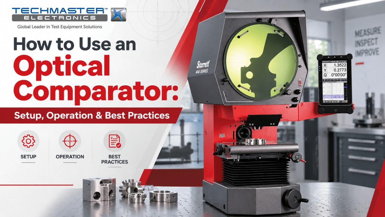
For quality control teams, machinists, and metrology technicians, learning how to use an optical comparator correctly is important for accurate part inspection. An optical comparator helps users measure profiles, angles, radii, and other part features without touching the workpiece.
However, several issues can affect measurement results. For example, lens distortion, poor stage alignment, and inaccurate digital readouts can cause inspection errors. As a result, manufacturers may reject good parts, accept bad parts, or face problems during quality audits.
Therefore, proper setup and operation are essential before starting a precision inspection.
1. Technical Principles: How an Optical Comparator Works
An optical comparator, also called a profile projector, projects a magnified image of a physical part onto a viewing screen. The operator can then inspect the part profile and compare it with drawings, overlays, or digital measurements.
First, a light source sends light through or around the workpiece. Next, the optical system magnifies the part image. Finally, mirrors project the image onto a ground-glass screen.
Many optical comparators use telecentric optics. This design keeps light rays nearly parallel through the measurement area. Therefore, the image size remains more stable when the part moves slightly within the focus range.
As a result, telecentric optics help reduce image errors caused by changes in part position.
Understanding Magnification Accuracy
Magnification accuracy is important because the projected image must match the actual part size at the selected lens setting.
For example, an optical comparator may use lenses with magnification levels such as:
- 10 times
- 20 times
- 50 times
- 100 times
The projected image should increase in size according to the selected lens power. Therefore, technicians often check magnification using a certified reference standard.
Magnification error can be calculated as:
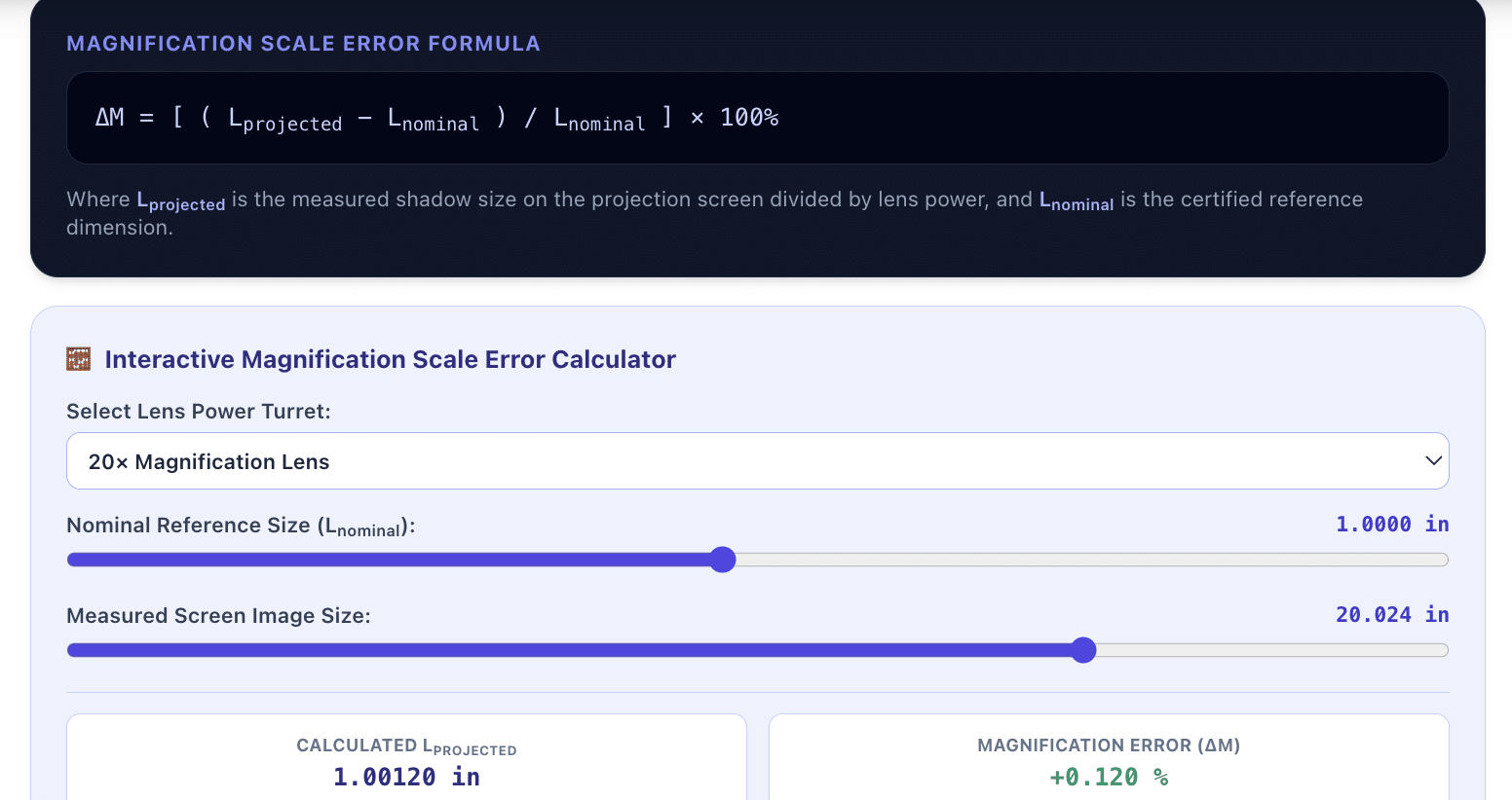
If the error becomes too large, the comparator may produce incorrect inspection results. Therefore, regular calibration is important.
2. Common Sources of Optical Comparator Measurement Error
Over time, normal use, temperature changes, and mechanical wear can affect measurement accuracy.
Therefore, operators should understand the most common sources of error before starting an inspection.
1. Optical Lens Distortion
First, lens distortion can change the shape or size of the projected image. For example, barrel or pincushion distortion may cause greater error near the edge of the screen. As a result, measurements taken near the outer viewing area may differ from measurements near the center.
Therefore, regular lens checks and calibration help maintain accurate results.
2. X/Y Stage Alignment Errors
The X and Y stage axes should remain perpendicular to each other. Ideally, the two axes form a 90℃ angle. However, mechanical wear or poor alignment can cause the axes to shift slightly.
As a result, the measured coordinates may become distorted, especially during long travel measurements.
3. Digital Readout and Scale Errors
Digital readouts measure movement along the X and Y axes. However, glass scales and other measuring parts can change slightly when temperature changes.
For this reason, temperature can affect measurement results during long inspection runs.
A basic temperature correction can be written as:

Here, α represents the material’s thermal expansion value.
Therefore, stable room conditions can help improve measurement accuracy.
3. How to Set Up and Operate an Optical Comparator
Proper setup is one of the most important parts of learning how to use an optical comparator.
Before measuring a part, operators should stabilize the instrument, clean the optical surfaces, and set a clear measurement reference.
Follow these steps for reliable profile inspection.
1. Power On and Allow the System to Stabilize
First, turn on the optical comparator and allow it to warm up for about 20 minutes.
During this time, the light source and internal parts can reach a more stable operating condition.
Meanwhile, inspect the projection screen, stage glass, and lenses.
Then, clean these surfaces with lint-free optical cloths.
This step helps remove dust, oil, and other material that may affect image quality.
2. Mount and Secure the Workpiece
Next, place the workpiece on the measurement stage.
Depending on the part shape, you may use a fixture, V-block, or other suitable support.
Make sure the part remains stable during measurement.
In addition, position the feature being measured correctly within the optical path.
Otherwise, poor positioning may make focusing and alignment more difficult.
3. Focus the Part Profile
Then, adjust the focus until the projected part edges appear sharp and clear.
A properly focused image should have clean edges without excessive blur.
If the image remains unclear, check the lens, workpiece position, and light path.
Additionally, make sure the part surface is clean before taking measurements.
4. Align the Crosshairs and Zero the Digital Readout
After focusing the image, align the screen crosshairs with a known part feature or reference edge.
Next, set the X/Y digital readout to the correct zero position.
This creates a reference point for later measurements.
Therefore, careful alignment at this stage helps prevent coordinate errors throughout the inspection process.
5. Measure Part Features
Finally, move the stage along the X and Y axes to measure the required features.
For example, an operator may measure:
- Linear distances
- Angles
- Radii
- Thread profiles
- Edge locations
- Part contours
Then, compare the results with the engineering drawing or inspection requirements.
If a measurement appears unusual, repeat the setup and check the focus, alignment, and zero point.
4. Best Practices for Accurate Optical Comparator Measurements
Following a few simple best practices can improve measurement consistency:
- First, always clean the lenses and stage before critical inspections.
- Next, allow the instrument to warm up before taking precise measurements.
- Additionally, make sure the workpiece is firmly supported and properly aligned.
- Operators should also avoid forcing the measurement stage because excessive force may affect positioning.
- Furthermore, use certified reference standards to check system performance on a regular basis.
- Finally, maintain a documented calibration schedule to support quality control requirements.
5. Industrial Applications of Optical Comparators
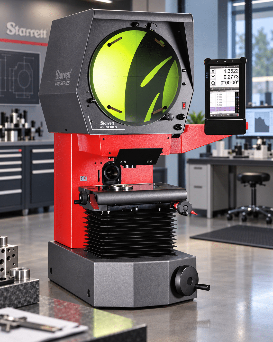
Optical comparators are widely used when manufacturers need accurate, non-contact inspection of part profiles.
Because the instrument does not require direct contact with many features, it is especially useful for small, delicate, or complex parts.
- Aerospace Manufacturing: In aerospace production, optical comparators can inspect turbine blade profiles, cooling features, edge shapes, and other precision parts. Therefore, they help manufacturers confirm that critical components match engineering requirements.
- Medical Device Manufacturing: Medical manufacturers use optical comparators to inspect small and detailed components. For example, technicians may check orthopedic screw threads, surgical needle angles, and other precision features. As a result, non-contact inspection can help protect delicate parts during measurement.
- Automotive Manufacturing: Automotive manufacturers use optical comparators to inspect fasteners, threads, chamfers, and precision engine components. Additionally, the equipment can support routine quality checks during production.
- Tooling and Precision Machining: Machine shops also use optical comparators to inspect cutting tools, stamping dies, punches, and other complex profiles. Therefore, the instrument remains a useful tool for both production and quality control.
Frequently Asked Questions
1. How often should an optical comparator undergo calibration?
An optical comparator should undergo accredited laboratory calibration every 12 months under standard shop-floor operating conditions to maintain ISO/IEC 17025 compliance and NIST traceability. However, units operating in high-vibration machining environments or used in 24/7 high-volume quality control lines require 6-month calibration intervals.
2. What causes magnification errors in precision optical comparators?
Magnification errors in optical comparators are primarily caused by optical lens distortion, misaligned mirror optics, incorrect lamp focal positioning, and thermal expansion of the instrument frame. Physical damage or oil residue on magnification lenses also alters light transmission and image sharpness.
3. What is the difference between daily shop-floor checks and ISO/IEC 17025 calibration?
Daily shop-floor checks are informal operator routines that clean optical glass and verify basic shadow alignment before taking measurements. ISO/IEC 17025 calibration is a formal laboratory evaluation that tests full-travel $X/Y$ scale linearity, magnification accuracy across all lenses, stage squareness, and protractor angular precision against NIST-traceable grid standards.
4. Why is X/Y stage squareness verification critical during optical comparator calibration?
Stage squareness verification is critical because angular misalignment between the horizontal and vertical travel axes distorts 2D coordinate calculations. If the X and Y axes are not orthogonal 90℃, measured part feature positions become geometrically skewed, leading to false inspection results.
5. How does ambient room temperature impact optical comparator measurement accuracy?
Ambient temperature changes cause thermal expansion in both the physical part being measured and the instrument’s cast-iron stage structure. Uncompensated thermal variations alter glass scale encoder pitches and expand metal parts, introducing linear measurement errors over extended inspection runs.
How to Use an Optical Comparator: Setup, Operation & Best Practices
An essential interactive guide for quality control managers, machinist inspectors, and dimensional metrologists. Master telecentric optics, magnification accuracy, X/Y stage squareness, thermal compensation, and ISO/IEC 17025 compliance.

Calibration engineer at Techmaster Electronics, ISO/IEC 17025 accredited laboratory with 35+ years of metrology expertise.