

What does infrared thermometer calibration actually verify?
An infrared (IR) thermometer never touches what it measures. It collects thermal radiation in a wide infrared band — typically 8–14 µm for handheld units — and infers temperature from the radiance it receives. That indirection is exactly why infrared thermometer calibration is a radiometric test, not a contact-thermometry test. Checking the sensor against a dry-block or liquid bath the way you would check a thermocouple or RTD probe tells you nothing about the optics, the detector, or the emissivity correction that dominate an IR reading.
The recognized method in the United States is ASTM E2847, Standard Test Method for Calibration and Accuracy Verification of Wideband Infrared Thermometers. It defines the calibration geometry (source, distance, alignment), how the reference radiance temperature is established, and how the laboratory must calculate and report measurement uncertainty. Instruments covered are direct-reading wideband IR thermometers used below 1,000 °C — which includes virtually every handheld “spot gun” from Fluke, Raytek, FLIR, Optris, and Omega used on plant floors today.
A proper calibration reports as-found readings, the reference radiance temperature, the emissivity setting used, the measuring distance and target aperture, and the expanded uncertainty. If a certificate is missing the emissivity setting or the geometry, the numbers on it cannot be reproduced — and an auditor who knows IR metrology will notice.
Why does emissivity decide whether your reading is right?
Every IR thermometer applies an emissivity correction before displaying temperature. A polished stainless tank may have an emissivity near 0.1; painted steel around 0.9; a purpose-built calibration cavity better than 0.999. When the instrument’s setting is wrong for the surface, the displayed temperature is wrong in a predictable direction: setting emissivity too high makes hot targets read low, and vice versa.
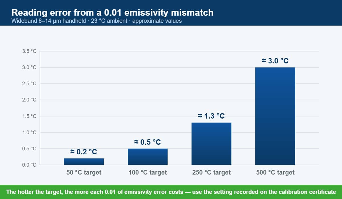
The practical consequence for calibration: the lab must record the emissivity setting used against its source, and you must use a consistent, documented setting in service. The table below shows the approximate reading shift caused by a small emissivity mismatch for a typical 8–14 µm handheld at 23 °C ambient — small at near-ambient temperatures, dominant at furnace temperatures.
| Target temperature | Approx. error per 0.01 emissivity mismatch | Practical impact |
|---|---|---|
| 50 °C | ≈ 0.2 °C | Minor for HVAC and food-holding checks |
| 100 °C | ≈ 0.5 °C | Visible against a ±1 °C process tolerance |
| 250 °C | ≈ 1.3 °C | Significant for molding and coating lines |
| 500 °C | ≈ 3 °C | Can consume an entire process tolerance |
Values are order-of-magnitude estimates for a wideband 8–14 µm instrument; the exact sensitivity depends on the detector band and ambient compensation.
This is also why “checking” an IR gun against a cup of hot coffee proves nothing: the emissivity of the coffee surface, steam, and the reflected background are all uncontrolled. Calibration requires a source whose emissivity is known to the third decimal place.
What is a blackbody calibration source?
National metrology institutes anchor the scale: NIST’s radiation thermometry program calibrates radiation thermometers against variable-temperature blackbodies whose temperatures are established with platinum resistance thermometers and detector-based methods. Accredited commercial labs replicate that chain: a contact standard (SPRT or PRT) or transfer radiation thermometer assigns the source temperature, and the IR thermometer under test is compared against it.
| Characteristic | Cavity blackbody | Flat-plate source |
|---|---|---|
| Effective emissivity | 0.995–0.9999 | ≈ 0.95 (coated plate) |
| Typical range | −40 °C to 1,000 °C+ (by model) | −30 °C to ≈ 500 °C |
| Aperture / target size | Small aperture (often 25–50 mm) | Large target (100–150 mm) |
| Best for | Lowest uncertainty, narrow-optics units | Handheld guns with wide fields of view |
| Emissivity handling | Reading taken near ε = 1.00 | Instrument set to plate’s calibrated ε (commonly 0.95) |
Neither design is “better” universally. A flat plate’s large target suits a 12:1 optics handheld at close range; a cavity delivers the emissivity certainty needed for tight-tolerance radiation thermometers. What matters is that the source’s radiance temperature, emissivity, and uniformity are characterized and traceable — the difference between a calibration and a demonstration.
What is the size-of-source effect — and why does D:S matter?
Manufacturers quote optics as a D:S ratio — 12:1 means a 25 mm spot at 300 mm distance. In reality the “spot” has soft edges: a real instrument still collects a few percent of its signal from an annulus around the nominal spot. Against a hot source in a cool room, that stray collection biases readings low; against a small target, dramatically so. ASTM E2847 requires the calibration geometry (distance and source aperture) to be reported precisely because two labs using different geometries can get legitimately different results on the same unit.
Field rule of thumb drawn from that physics: keep the target at least twice the nominal spot diameter, center it, and get closer rather than farther whenever the surface allows. A 12:1 gun reading a 20 mm bearing housing from 1 m away is measuring mostly wall, not bearing.
Which calibration points and tolerances should you request?
Point selection follows the same logic as any calibration: bracket the range you rely on, and add the specific process temperature if your tolerance there is tight. Common patterns we see across Techmaster’s customer base:
| Application | Typical points | Typical tolerance applied |
|---|---|---|
| General maintenance handheld (e.g., Fluke 62 MAX+) | 0 °C / 100 °C / 400 °C | ±1.5 °C or ±1.5% of reading |
| Food safety spot checks | −18 °C / 4 °C / 100 °C | ±1 °C class instruments |
| Process / fixed-mount pyrometer | 3–5 points across loop range | Manufacturer spec or process tolerance |
| Precision radiation thermometer (e.g., Fluke 568) | Multiple points, cavity source | ±1 °C or better |
Ask the lab to report as-found and as-left data with uncertainty at each point, so your reliability analysis and interval-setting method have real evidence to work from. If the certificate will feed a decision rule (pass/fail with guard banding), say so when you place the order — the tolerance and uncertainty must be evaluated together.
How does an ISO/IEC 17025 lab calibrate an IR thermometer?
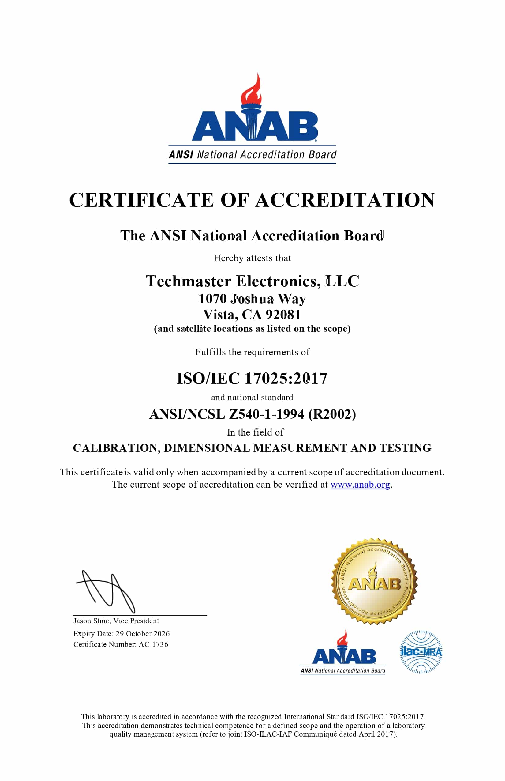
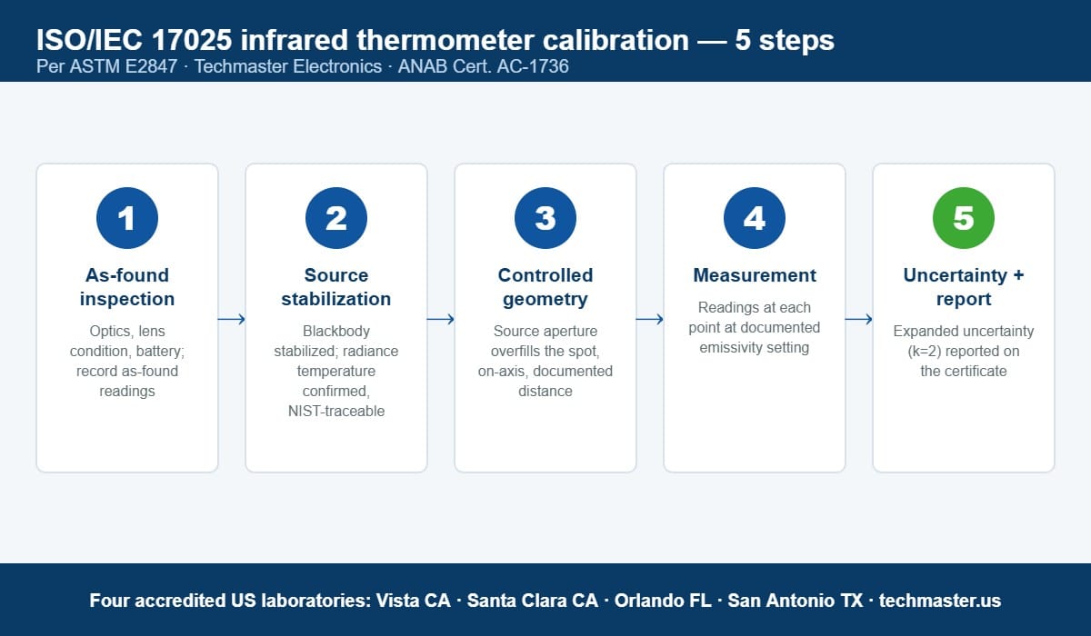
At Techmaster Electronics — an ISO/IEC 17025 accredited calibration laboratory (ANAB Cert. AC-1736) serving US industry since 1989 — thermodynamic calibration follows this sequence:
1. Incoming inspection and as-found. Optics are checked for lens damage and contamination (a dirty germanium lens reads low), the battery and display are verified, and as-found readings are taken before any adjustment.
2. Source stabilization. The blackbody is stabilized and its radiance temperature confirmed against the lab’s reference standards, traceable to NIST.
3. Controlled geometry. Distance is set so the source aperture overfills the instrument’s spot with margin, on-axis, per ASTM E2847.
4. Measurement. Readings at each point are recorded at the documented emissivity setting, with ambient temperature logged for reflected-background correction.
5. Uncertainty and reporting. Source emissivity, uniformity and stability, reference standard uncertainty, SSE, and instrument resolution are combined into the expanded uncertainty (k=2) reported on the certificate.
That uncertainty line is what separates the three service levels customers order: a traceable calibration with certificate, a Z540-style calibration with data, or a full ISO/IEC 17025 accredited calibration with data and uncertainties. Across the 381,916 calibrations Techmaster performed in the last ten years — spanning 4,913 manufacturers — temperature instruments are consistently among the highest-volume workload, and IR guns are the units most often returned with an emissivity setting nobody could explain. Recording the setting on the certificate ends that ambiguity.
Techmaster performs thermodynamic calibration at its accredited laboratories in Vista CA, Santa Clara CA, Orlando FL, and San Antonio TX, with free local pickup and delivery in Silicon Valley, Southern California, and Orlando. See the full calibration services overview for the other eleven disciplines.
How often should you calibrate an infrared thermometer?
IR thermometers have no probe to age the way a thermocouple drifts, but they do fail in their own ways: scratched or contaminated optics, detector aging, drop damage that shifts alignment, and firmware-level emissivity settings changed by borrowers. Because most failures are event-driven rather than gradual, as-found history is especially valuable — an instrument that arrives in tolerance three cycles running is a candidate for extension under the analysis methods in ILAC’s guidance series (ILAC-G24), while any dropped or lens-damaged unit should come in immediately regardless of date.
Cost context: a single-band handheld calibration is inexpensive relative to the decisions it protects — verifying a mold temperature, releasing a food batch, or clearing an overheating breaker panel. One bad reading that ships product costs more than a decade of calibrations.
Key takeaways
• Infrared thermometer calibration is a radiometric comparison against a blackbody source per ASTM E2847 — a dry-block check does not qualify.
• Emissivity mismatch is the dominant field error: roughly 0.5 °C per 0.01 at 100 °C, several degrees at 500 °C. Use the setting recorded on the certificate.
• Cavity blackbodies offer ε ≥ 0.995 for lowest uncertainty; flat plates (ε ≈ 0.95) suit wide-field handhelds.
• The size-of-source effect means your target should overfill the nominal D:S spot by at least 2×.
• Request three or more points spanning your use range with as-found/as-left data and uncertainty.
• Techmaster Electronics (ISO/IEC 17025, ANAB Cert. AC-1736, founded 1989) calibrates IR thermometers at four accredited US laboratories.
Frequently asked questions
What emissivity setting should be used during infrared thermometer calibration?
The setting that matches the source: near 1.00 for a cavity blackbody, or the plate’s calibrated value — commonly 0.95 — for a flat-plate source. The certificate must state the setting used, and in service you should either use that same setting or apply a documented correction for your surface.
Can I check an infrared thermometer with an ice bath?
A properly made ice-point slush gives a rough functional check near 0 °C because water’s emissivity is high, but it is not a calibration: emissivity, geometry, and reflected background are uncontrolled, and one point says nothing about the rest of the range. Use it to catch gross failure between calibrations, not to replace them.
How often should an infrared thermometer be calibrated?
Start at 12 months for general industrial use and 6 months for food-safety or regulated applications, then adjust using as-found history per ILAC-G24 methods. Recalibrate immediately after any drop, lens damage, or reading that disagrees with a trusted contact thermometer.
What accuracy can a handheld IR thermometer achieve after calibration?
Calibration verifies the manufacturer’s specification — typically ±1 °C to ±2 °C or 1–2% of reading for handhelds — it does not improve it. Laboratory expanded uncertainties for flat-plate calibrations are commonly a few tenths of a degree to about 1 °C, so the spec, not the lab, is usually the limiting factor.
Why does my IR gun and my contact probe disagree?
Usually emissivity: the gun’s setting doesn’t match the surface, especially on shiny metal. Other causes are the size-of-source effect (target smaller than the measuring spot), reflected radiation from hot surroundings, steam or dust in the sight path, and a contaminated lens. If both instruments are in calibration, the disagreement is diagnostic information about the measurement, not the tools.
Do thermal imaging cameras calibrate the same way?
The physics is identical — blackbody references, emissivity, and geometry — but imagers are calibrated across the focal-plane array and often at multiple ranges, so the procedure and uncertainty budget are more involved. If your camera output feeds quality records, it needs the same traceable calibration discipline as a spot thermometer.
Need an infrared thermometer calibrated with accredited uncertainty data?
ISO/IEC 17025 accredited calibration laboratory · ANAB Cert. AC-1736 · Since 1989 · Labs in California, Florida, and Texas
Request a Calibration Quote
Khanh Nguyen is the Marketing Manager at Techmaster Electronics, a B2B marketing leader covering the test, measurement, and ISO/IEC 17025 accredited calibration industry across the US and Vietnam markets.