
Function Waveform Generator Calibration: ISO/IEC 17025 Step-by-Step Guide
1. Why Function Waveform Generator Calibration Matters
- False acceptance: An incorrect test signal may cause an engineer to accept a device that does not meet its design requirements.
- False rejection: An inaccurate signal may cause a good device to fail a test, leading to extra checks and wasted production time.
2. How to Calibrate a Function Waveform Generator: Step-by-Step Guide
The exact procedure depends on the generator model, its specifications, and the laboratory’s calibration method. Therefore, qualified technicians should follow the manufacturer’s instructions and the laboratory’s approved procedures.Step 1: Inspect the Generator and Test Cables
First, check the generator’s case, display, controls, output connectors, and power cable. Next, inspect the coaxial cables and adapters for worn insulation, loose connectors, or damaged center pins. Also, confirm the required output impedance and load setting before making any connections. For example, some instruments use a 50-ohm output setting. However, the correct setup depends on the model and the test method.Step 2: Allow the Equipment to Stabilize
Next, power on the generator and the reference instruments according to their manuals. Allow enough time for each device to reach its specified operating condition. For example, a laboratory may use a controlled temperature and a set warm-up period. However, do not assume that every generator requires the same temperature or a fixed 30-minute warm-up. Instead, follow the manufacturer’s guidance and the approved calibration procedure.Step 3: Check Frequency Accuracy
After the equipment stabilizes, connect the generator output to a suitable calibrated frequency counter. Then, select test frequencies that cover the required operating range. Record the generator’s displayed frequency and compare it with the reference reading. Next, calculate the difference and check it against the applicable tolerance. For high-accuracy work, the laboratory should select a reference with suitable accuracy and traceability. An atomic reference may suit some applications; however, not every calibration requires a rubidium standard.Step 4: Check Output Amplitude
Next, set the generator to the required waveform, frequency, and output level. Connect it to a suitable calibrated instrument, such as an oscilloscope or voltage measurement system. Then, compare the measured output with the set value. Repeat the check at selected levels and frequencies across the required range. This step helps the technician identify output errors and changes in amplitude with frequency. However, the test setup must match the instrument’s specifications. For example, a 50-ohm termination may be necessary for some tests, while other setups may require a different load.Step 5: Check DC Offset and Waveform Quality
If the generator supports DC offset, check the output at suitable positive, negative, and zero settings. Then, compare the readings with the applicable limits. In addition, inspect the waveform for unwanted distortion when the calibration scope includes waveform quality. For sine waves, a suitable analyzer may measure total harmonic distortion (THD). For square waves, the procedure may include rise time, fall time, or other signal characteristics. However, the exact tests depend on the generator’s design and the service scope. Therefore, do not assume that every calibration includes all waveform types or every performance parameter.Step 6: Record the Results
Finally, record the test conditions, reference equipment, measured values, and applicable limits. Where the service reports them, review both the as-found and as-left results. If a reading falls outside the allowed limit, the technician should document the result and follow the approved process for adjustment or repair. After any adjustment, the laboratory should perform the required checks and report the final results. These records help teams assess instrument performance and make informed decisions about future calibration intervals.3. Daily Checks vs. Accredited Calibration
Routine checks and accredited calibration serve different purposes. A daily check can help confirm that the generator works as expected. However, accredited calibration provides a more formal assessment of selected performance parameters against suitable reference standards.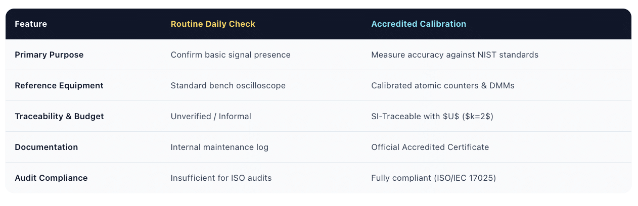 Therefore, routine checks should support, rather than replace, calibration when documented calibration is required. In addition, organizations should confirm that the requested service falls within the laboratory’s accredited scope if they need accredited results.
Techmaster US: Function Waveform Generator Calibration Services
Techmaster Electronics, LLC is an ISO/IEC 17025 accredited calibration laboratory with ANAB certificate AC-1736. Founded in 1989, the company serves customers through laboratories in Vista, California; Santa Clara, California; Orlando, Florida; San Antonio, Texas; and Holly Springs, North Carolina. Its corporate offices are in Vista, California, and Henderson, Nevada. Techmaster US provides calibration services for electrical, electronic, RF/microwave, dimensional, and mechanical test equipment within its applicable service scope. Depending on the instrument and requested service, customers can ask about calibration options for function waveform generators and related test equipment. In addition, Techmaster US offers mobile on-site calibration when the requested service falls within the laboratory’s accredited scope. Customers can contact the team to confirm service availability, turnaround options, and the required test parameters. To help identify the right service, provide the generator’s manufacturer, model, frequency range, output specifications, and calibration requirements. This information helps the team review the available options.Frequently Asked Questions (FAQs)
1. What is function waveform generator calibration?Function waveform generator calibration compares an instrument’s output with suitable reference standards. Depending on the model and service scope, the process may check frequency accuracy, output amplitude, DC offset, and waveform quality. As a result, users can assess whether the generator meets the required limits.
2. How often should a function waveform generator be calibrated?The right interval depends on manufacturer guidance, usage, environment, calibration history, and measurement risk. For example, a laboratory may choose a 12-month interval as a starting point. However, some applications may need more frequent calibration if the instrument shows drift or works under demanding conditions.
3. What causes frequency drift in a waveform generator?Frequency drift can result from changes in the internal reference oscillator, temperature effects, aging components, or other circuit changes. In direct digital synthesis (DDS) generators, the reference clock can affect the frequencies the system produces. Therefore, regular performance checks can help identify unwanted changes.
4. Can internal self-calibration replace accredited calibration?No. Internal self-calibration can correct certain errors within the limits of the instrument’s design. However, it does not necessarily verify absolute frequency accuracy, output amplitude, or waveform quality against external reference standards. When you need documented calibration results, use a suitable calibration service.
5. What parameters does calibration check?The parameters depend on the generator and the agreed calibration scope. For example, a procedure may check frequency accuracy, output amplitude, and DC offset. In addition, it may check THD, rise time, fall time, or other waveform characteristics when relevant.
6. Does ISO/IEC 17025 require calibration every 12 months?No. ISO/IEC 17025 does not set one fixed interval for all waveform generators. Instead, organizations should consider equipment performance, manufacturer guidance, measurement risk, and applicable quality requirements when choosing a calibration schedule.
Conclusion
Function waveform generator calibration helps engineers check signal accuracy and maintain reliable test results. By reviewing frequency, amplitude, and other relevant parameters, teams can identify errors before they affect product testing or production decisions. Therefore, choose a calibration interval that reflects the instrument’s use, environment, and performance history. In addition, keep clear calibration records and work with a suitable laboratory when your quality system requires documented or accredited results.Function Waveform Generator Calibration Guide
Function waveform generators synthesize sine, square, ramp, and arbitrary signals essential for electronics testing. Internal clock drift, DAC non-linearity, and output amplifier changes can compromise measurement integrity over time. Learn how ISO/IEC 17025 accredited calibration ensures traceably accurate signals.
CONTACT USFrequently asked questions
What is function waveform generator calibration?
Function Waveform Generator Calibration is the documented comparison of a function waveform generator against NIST-traceable reference standards under ISO/IEC 17025. It quantifies the function waveform generator’s error and measurement uncertainty and confirms it performs within tolerance, with as-found and as-left data on the certificate.
How often should a function waveform generator be calibrated?
Most quality systems calibrate a function waveform generator every 12 months, or sooner after repair, overload, or before critical measurements. Set your interval from the manufacturer spec and your ISO 9001 / 13485 / AS9100 program and drift history.
Is Techmaster’s function waveform generator calibration ISO 17025 accredited?
Yes. Techmaster Electronics is ISO/IEC 17025:2017 accredited by ANAB (Certificate AC-1736). Every function waveform generator calibration is NIST-traceable and issued with a full measurement-uncertainty budget.
What is the turnaround for function waveform generator calibration?
Standard turnaround is 5 business days, with 1–2 business-day expedite available. On-site calibration removes shipping time entirely for function waveform generators that can’t leave the floor.
Do you calibrate function waveform generators on-site or in-lab?
Both. Techmaster runs five US labs (Vista CA, Santa Clara CA, Orlando FL, San Antonio TX, Holly Springs NC) and offers nationwide on-site function waveform generator calibration to minimize downtime.
References & industry standards
- ISO/IEC 17025 testing & calibration laboratory requirements
- NIST calibration services and measurement traceability
- A2LA / ANAB accreditation for calibration laboratories
External standards bodies. Techmaster Electronics is an ISO/IEC 17025-accredited, NIST-traceable calibration laboratory.

Calibration engineer at Techmaster Electronics, ISO/IEC 17025 accredited laboratory with 35+ years of metrology expertise.