

How to Use a Curve Tracer Analyzer: Setup, Operation & Best Practices

Understanding how to use a curve tracer analyzer correctly is important for solar field engineers, O&M technicians, and PV commissioning teams. A curve tracer measures the current-voltage (I-V) response of a PV module or string under a controlled sweep. As a result, it helps teams check power output, wiring, shading, and other performance issues. In practice, correct setup is just as important as the test itself. Therefore, users should follow the instrument manual, use the correct leads and sensors, check site conditions, and follow all high-voltage safety rules. Regular calibration also helps keep measurement results reliable.
1. Technical Principles: I-V Sweeping, 4-Wire Sensing, and Measurement Drift
1.1. Physics of Photovoltaic I-V Curve Tracing
A PV curve tracer uses an electronic or capacitive load to sweep the operating point of a solar module or string. During the sweep, the analyzer records voltage and current at many points. It then creates both the Current-Voltage (I-V) and Power-Voltage (P-V) curves.
The analyzer can then determine several key PV values, including:
- Open-Circuit Voltage (Voc)
- Short-Circuit Current (Isc)
- Maximum Power Point Voltage (Vmpp)
- Maximum Power Point Current (Impp)
- Maximum Power Output (Pmpp)
The maximum power point follows this formula:
Pmpp = Vmpp × Impp
In addition, the analyzer can calculate the Fill Factor (FF). This value compares the maximum power point with the product of open-circuit voltage and short-circuit current.
FF = (Vmpp × Impp) / (Voc × Isc)
Therefore, FF can help engineers compare PV performance and identify changes in the shape of the I-V curve.
1.2. Why Lead Resistance Matters
During a high-current test, test leads and contact points can add resistance. Consequently, the measured voltage may differ from the actual voltage at the PV terminals.
For example:
Voltage Drop = Current × Resistance
Because of this, many curve tracer systems use separate current and voltage connections. This approach is often called 4-wire Kelvin sensing.
With this setup, the current leads carry the test current. Meanwhile, the voltage sense leads measure the voltage directly at the test point. Since the voltage input draws very little current, the sense leads add much less voltage drop.
However, 4-wire sensing does not remove every source of measurement error. Contact quality, lead condition, sensor accuracy, instrument limits, and site conditions can still affect the result.
For this reason, users should inspect all connections before starting a sweep.
1.2. Understanding Measurement Drift
Curve tracer accuracy can change over time. Several factors can contribute to this change.
First, voltage reference drift can affect voltage readings. Temperature and long-term component aging may change the reference used by the measurement circuit.
Next, current measurement components can change with temperature and repeated use. As a result, current readings may shift from their original values.
In addition, switching components in the load section can age after repeated high-energy tests. This change may affect sweep control or curve shape.
Finally, irradiance and temperature sensors can drift. This matters because PV test results often depend on irradiance and module temperature. Poor sensor accuracy can lead to incorrect performance corrections.
Therefore, regular checks and calibration are important when measurement results support commissioning, maintenance, or warranty decisions.
2. How to Use a Curve Tracer Analyzer in the Field
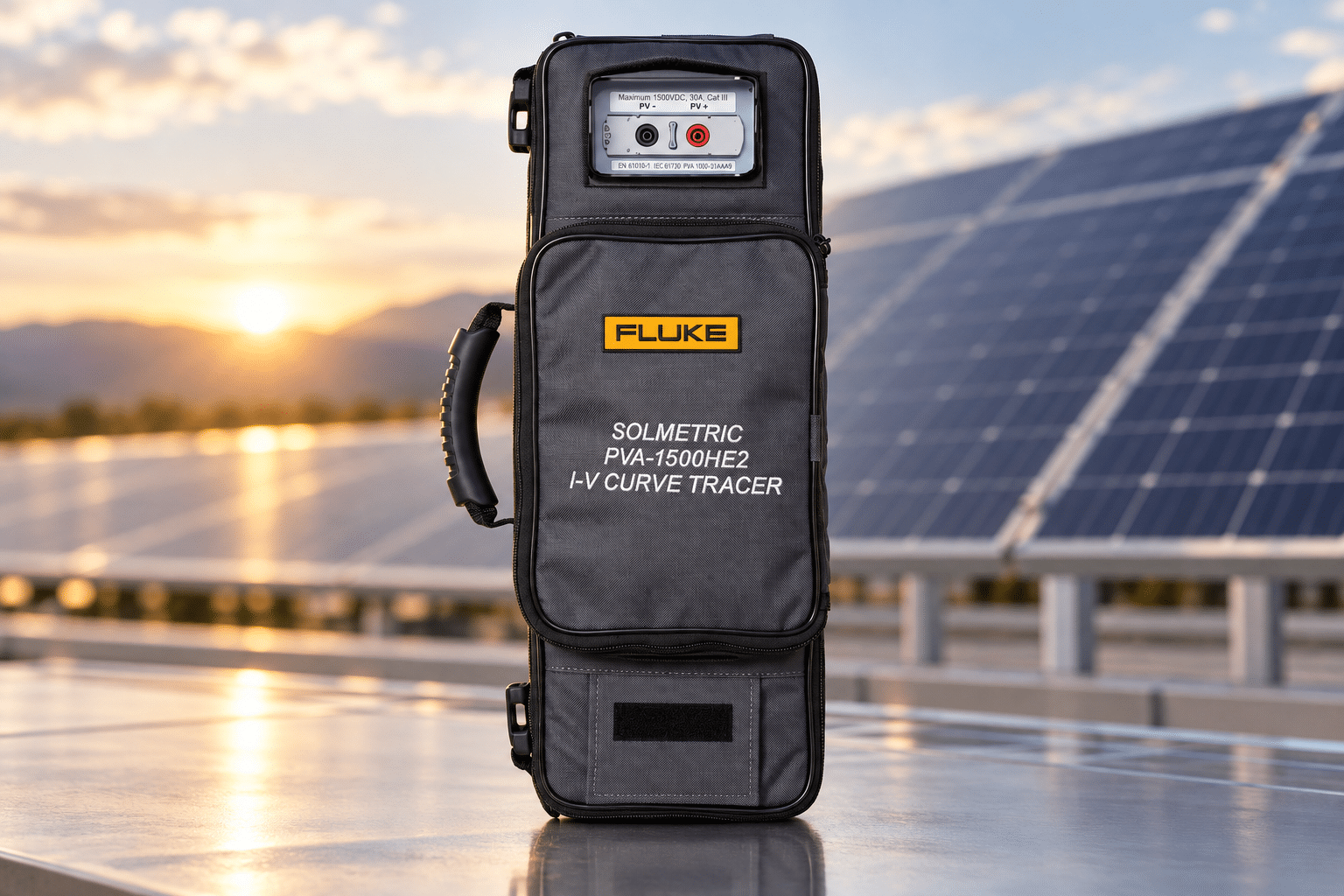
Knowing how to use a curve tracer analyzer starts with a controlled test setup. The exact steps vary by instrument, so always follow the manufacturer’s instructions.
1. Inspect the Equipment
First, inspect the curve tracer, test leads, connectors, current sensors, and temperature or irradiance sensors.
Look for:
- Damaged insulation
- Loose connectors
- Broken cables
- Dirty contacts
- Damaged sensor cables
- Signs of overheating
Also, check that the instrument has enough battery power and storage space for the planned tests.
2. Check the PV System
Next, identify the PV module or string that you will test.
Before connecting the analyzer, confirm:
- The expected system voltage
- The expected current
- The string configuration
- The connector type
- The required test points
- The safe working limits of the instrument
This step is especially important for high-voltage PV systems.
3. Check Site Conditions
PV conditions can change during the test. Therefore, record the main test conditions, including irradiance, module temperature, and ambient temperature when required.
For example, clouds can cause rapid irradiance changes. Likewise, module temperature can change during the day.
As a result, two tests taken at different times may produce different curves even when the PV system has not changed.
4. Connect the Test Leads
Then, connect the current and voltage leads according to the instrument manual.
If the instrument uses separate current and voltage connections, make sure each lead goes to the correct terminal.
Also, inspect the connectors before starting the test. A loose or poor connection can create unstable readings and may increase safety risk.
5. Connect the Sensors
Next, connect the irradiance and temperature sensors if the test requires them.
Place the irradiance sensor so that it sees the same sunlight as the PV surface being tested. In addition, place the temperature sensor correctly on the module according to the manufacturer’s procedure.
Because environmental conditions affect PV output, accurate sensor placement is important.
6. Perform the I-V Sweep
Once the setup is complete, start the I-V sweep from the instrument interface.
During the sweep, the analyzer changes the electrical load and records voltage and current.
The result is an I-V curve that shows how the PV source behaves across its operating range.
The analyzer can also calculate the P-V curve and key values such as Voc, Isc, Vmpp, Impp, and Pmpp.
7. Review the Curve
After the sweep, review the curve before moving to the next string.
Look for unusual features such as:
- Steps
- Notches
- Unexpected drops
- Low current
- Low voltage
- Reduced maximum power
- Unusual curve shape
However, do not assume that every unusual curve has the same cause. Instead, compare the result with site conditions, system design, previous measurements, and the manufacturer’s guidance.
8. Save and Compare the Results
Finally, save the test data with clear information about the string, location, date, and test conditions.
Then, compare the result with previous measurements or expected system values.
Over time, this data can help teams identify performance changes and support maintenance decisions.
2. Common Industrial Applications
Curve tracer analyzers support several PV testing tasks. For example, teams can use them during commissioning, maintenance, troubleshooting, and warranty work.
2.1. Utility-Scale PV Commissioning
First, commissioning teams can test PV strings before a plant enters service.
The results can help verify:
- String voltage
- String current
- Maximum power
- Wiring
- Unexpected curve changes
- Differences between strings
As a result, teams can find issues before they affect long-term plant operation.
2.2. PV Module Testing
Next, manufacturers and test teams can use I-V testing to evaluate module performance.
For example, the results can help identify differences between modules, wiring problems, or other performance issues.
The exact test method depends on the equipment and the required test standard.
2.3. PV and Battery System Checks
In addition, some hybrid energy systems combine PV generation with battery storage.
In these systems, PV measurements can help engineers understand the DC source before it connects to the inverter or storage system.
However, a PV curve tracer should only be used within its rated voltage, current, and measurement range.
2.4. O&M and Warranty Diagnostics
Finally, curve tracers can support troubleshooting and warranty investigations.
Teams can compare current I-V curves with earlier results. Therefore, they may identify changes linked to shading, wiring issues, module mismatch, bypass diode problems, or other faults.
The curve alone does not always identify the exact cause. Instead, engineers should combine curve data with visual inspection and other test results.
Frequently Asked Questions
1. What is a photovoltaic curve tracer analyzer?
A photovoltaic curve tracer analyzer is a specialized high-voltage electronic instrument designed to measure and plot the current-voltage ($I$–$V$) characteristic curve of solar panels and PV strings under dynamic loading conditions.
2. How often should a curve tracer analyzer be calibrated?
A curve tracer analyzer should be calibrated at least once every 12 months under standard field conditions. Instruments deployed in heavy utility-scale commissioning, extreme ambient environments, or continuous daily sweeps should undergo calibration every 6 months to prevent electronic reference drift.
3. Why is 4-wire Kelvin sensing required when using a curve tracer?
4-wire Kelvin sensing separates high-current drive leads from high-impedance voltage sense leads. This arrangement eliminates voltage drops across test lead wires and contact points, ensuring accurate open-circuit voltage (Voc) and short-circuit current (Isc) measurements.
4. What causes steps or notches in an I – V curve measurement?
Steps or notches in an I – V curve indicate partial shading across solar cells, malfunctioning bypass diodes, or cracked solar cells that force string current to bypass affected module sections during dynamic loading.
5. Can field lead zeroing replace laboratory calibration?
No, field lead zeroing only compensates for cable resistance and baseline offsets. It cannot adjust or verify internal ADC voltage divider linearity, current shunt thermal decay, or wireless sensor calibration parameters, which require accredited laboratory standards.
6. Does Techmaster US calibrate curve tracer analyzers on-site?
Yes, Techmaster Electronics provides ISO/IEC 17025 accredited on-site calibration services for curve tracer analyzers, insulation resistance testers, and solar commissioning tools across the United States. Our mobile metrology teams bring NIST-traceable standards directly to your job site or facility.
Frequently asked questions
What is curve tracer analyzer calibration?
Curve Tracer Analyzer Calibration is the documented comparison of a curve tracer analyzer against NIST-traceable reference standards under ISO/IEC 17025. It quantifies the curve tracer analyzer’s error and measurement uncertainty and confirms it performs within tolerance, with as-found and as-left data on the certificate.
How often should a curve tracer analyzer be calibrated?
Most quality systems calibrate a curve tracer analyzer every 12 months, or sooner after repair, overload, or before critical measurements. Set your interval from the manufacturer spec and your ISO 9001 / 13485 / AS9100 program and drift history.
Is Techmaster’s curve tracer analyzer calibration ISO 17025 accredited?
Yes. Techmaster Electronics is ISO/IEC 17025:2017 accredited by ANAB (Certificate AC-1736). Every curve tracer analyzer calibration is NIST-traceable and issued with a full measurement-uncertainty budget.
What is the turnaround for curve tracer analyzer calibration?
Standard turnaround is 5 business days, with 1–2 business-day expedite available. On-site calibration removes shipping time entirely for curve tracer analyzers that can’t leave the floor.
Do you calibrate curve tracer analyzers on-site or in-lab?
Both. Techmaster runs five US labs (Vista CA, Santa Clara CA, Orlando FL, San Antonio TX, Holly Springs NC) and offers nationwide on-site curve tracer analyzer calibration to minimize downtime.

Calibration engineer at Techmaster Electronics, ISO/IEC 17025 accredited laboratory with 35+ years of metrology expertise.