

What is the difference between a thermocouple and an RTD?
The two technologies dominate industrial temperature measurement, and the choice between them shapes your entire calibration program. A Type K or Type J thermocouple is a self-powered sensor: two alloy wires welded at the tip produce roughly 41 µV/°C (Type K), which a readout converts to temperature using the reference functions published in the NIST ITS-90 thermocouple database (SRD 60). An RTD is a passive resistor, 100 Ω of high-purity platinum at 0 °C for a Pt100, whose resistance-temperature relationship is standardized in IEC 60751:2022.
That structural difference drives everything that follows: accuracy class, drift behavior, usable range, and how an ISO/IEC 17025 laboratory calibrates each one. Techmaster Electronics has calibrated temperature instruments since 1989, and thermodynamic work, sensors, dry-blocks, baths, indicators, and controllers, is one of the largest disciplines in our 10-year dataset of 381,916 completed calibrations.
Which is more accurate: thermocouple or RTD?
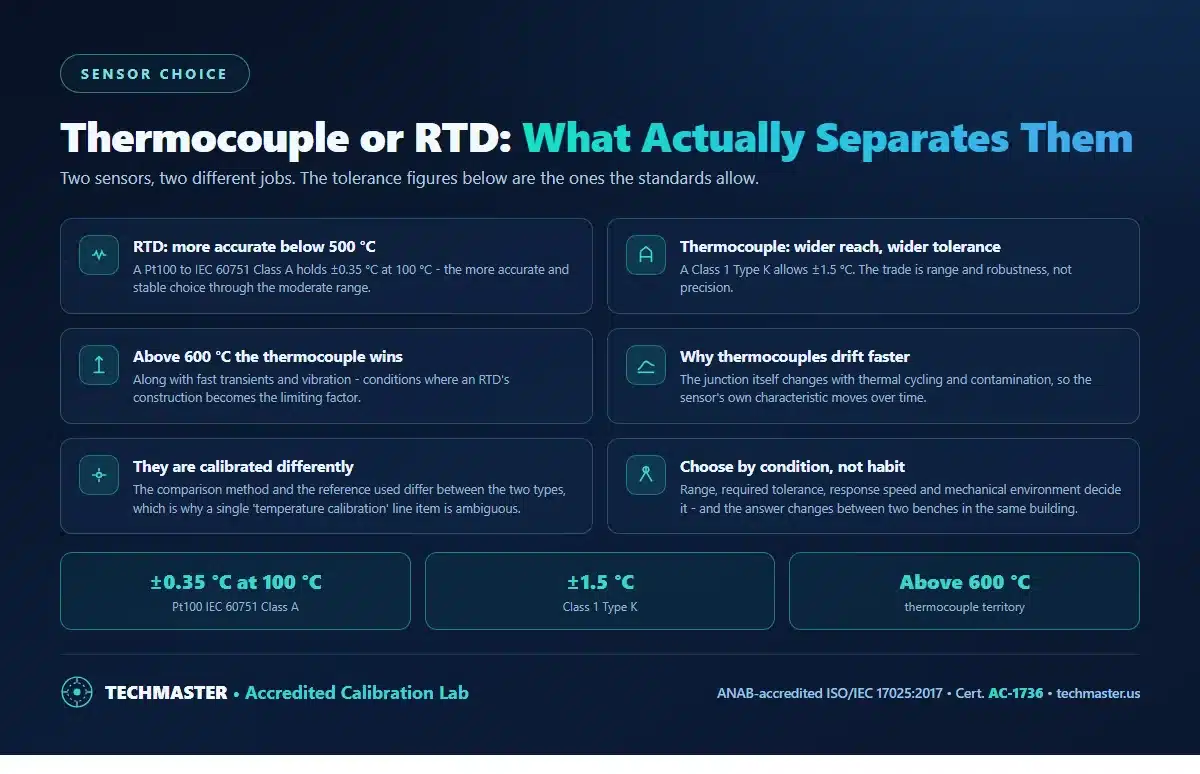
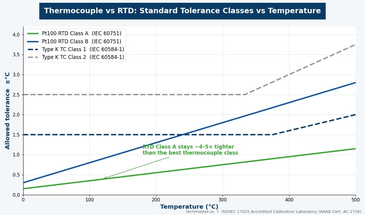
The tolerance classes below come straight from the two governing standards, IEC 60751:2022 for platinum RTDs and IEC 60584-1 for letter-designated thermocouples. These are as-new manufacturing tolerances; real-world error grows with drift, insertion effects, and readout uncertainty, which is why periodic accredited calibration matters.
| Sensor & class | Tolerance formula | At 100 °C | At 400 °C |
|---|---|---|---|
| Pt100 RTD, Class AA | ±(0.10 + 0.0017·|t|) °C | ±0.27 °C | , (range limited) |
| Pt100 RTD, Class A | ±(0.15 + 0.002·|t|) °C | ±0.35 °C | ±0.95 °C |
| Pt100 RTD, Class B | ±(0.30 + 0.005·|t|) °C | ±0.80 °C | ±2.30 °C |
| Type K TC, Class 1 | ±1.5 °C or ±0.004·|t| | ±1.5 °C | ±1.6 °C |
| Type K TC, Class 2 | ±2.5 °C or ±0.0075·|t| | ±2.5 °C | ±3.0 °C |
Two practical notes. First, Class AA is only defined over a restricted range (typically −50 °C to +250 °C for wire-wound elements), so it is not available for high-temperature service. Second, a sensor is only as good as the loop reading it: a 0.35 °C-class RTD paired with a 1 °C-class panel indicator is a 1 °C loop. That is why Techmaster calibrates the sensor, the readout, or the loop end-to-end, whichever matches how you use it.
Why do thermocouples drift more than RTDs?
Drift is the hidden cost of thermocouples. Every hour at elevated temperature slowly changes the wire alloys, and because the Seebeck voltage is generated along the entire gradient zone, inhomogeneous wire produces different errors depending on immersion depth, a drifted thermocouple can even pass a spot-check at one depth and fail in service at another. Common failure mechanisms our thermodynamic lab sees include Type K green rot (chromium depletion in low-oxygen atmospheres), Type J iron-leg oxidation above 500 °C, and contamination through compromised sheaths.
RTDs fail differently: mechanical shock and vibration crack the platinum element or shift its strain state, and moisture ingress changes insulation resistance. The result is usually a step change or erratic reading rather than slow silent drift, easier to catch, but still a reason the element belongs on a scheduled calibration program. For a deeper look at verifying thermocouple health, see our guide to thermocouple calibration by comparison vs fixed-point methods.
How are thermocouples and RTDs calibrated differently?
In an ISO/IEC 17025 accredited comparison calibration, the unit under test and a reference probe, typically a secondary-standard PRT such as a Fluke 5608/5609 read by a precision thermometry bridge or a Fluke 1586A Super-DAQ, are placed in the same isothermal zone and compared at several points across the working range. For RTDs, an accredited RTD calibration can go beyond a pass/fail check and fit individual Callendar–Van Dusen or ITS-90 coefficients, often improving a Class B probe’s realized accuracy by 5–10× when the coefficients are loaded into the readout.
Thermocouple calibration adds two complications. The reference junction must be controlled, an ice point or electronically compensated junction, and the immersion depth must place the full gradient zone in representative conditions, or wire inhomogeneity will bias the result. Above 660 °C, comparison work moves to tube furnaces with noble-metal (Type S/R) references. Techmaster performs accredited thermodynamic calibration under ANAB certificate AC-1736 at our ISO/IEC 17025 thermodynamic calibration laboratories, part of our full electronic test equipment calibration scope across Vista CA, Santa Clara CA, Orlando FL, and San Antonio TX.
How often should you recalibrate temperature sensors?
ILAC-G24:2022, Guidelines for the determination of recalibration intervals of measuring equipment, describes interval-setting methods, calendar time, usage hours, and control-chart methods driven by as-found data. The practical rule for temperature sensors: interval length should follow drift risk. A Type K thermocouple cycling daily to 900 °C may deserve quarterly verification; a panel-mounted Pt100 in an HVAC loop can safely run annual. Your as-found history is the evidence, if three consecutive certificates show the sensor well inside tolerance, ILAC-G24 supports extending; any out-of-tolerance result argues for shortening and for a reverse-traceability review of product tested since the last good calibration.
We covered the interval-setting math in detail in our reliability-based guide to setting calibration intervals.
Which sensor should you choose for your application?
| Criterion | RTD (Pt100) | Thermocouple (K/J/N) |
|---|---|---|
| Best accuracy (as-new) | ±0.1–0.35 °C | ±1.1–2.5 °C |
| Usable range | −200 to +850 °C (practical <500 °C) | −200 to +1700 °C (type-dependent) |
| Typical drift | <0.1 °C/year | 1–3 °C/year in hot service |
| Response time | Slower (larger mass) | Fast (small grounded junctions) |
| Vibration tolerance | Lower (element fragility) | High |
| Sensor cost | Higher | Lower (often consumable) |
| Calibration approach | Comparison vs reference PRT; CVD coefficients | Comparison with reference junction control; frequent verification |
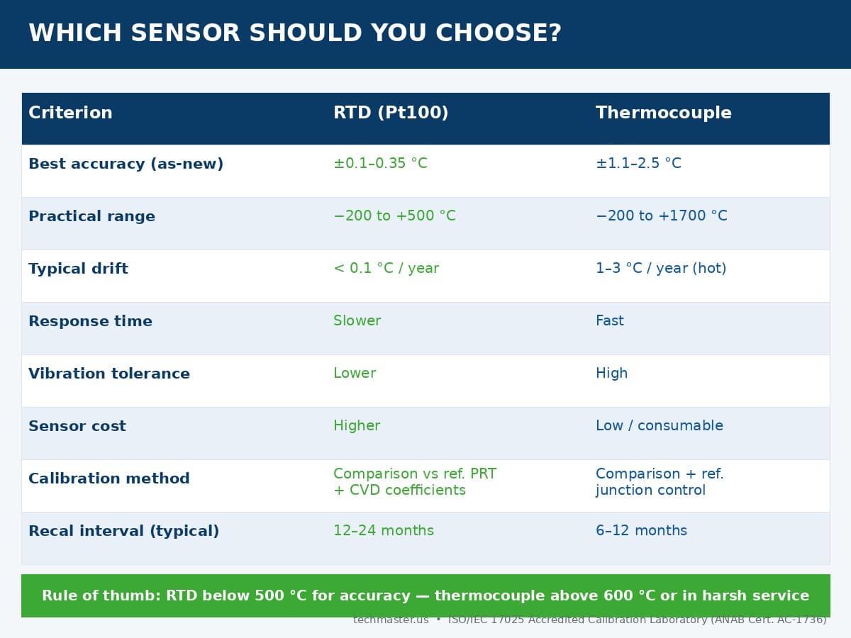
Many plants run both: RTDs at custody-transfer and quality-critical points, thermocouples in furnaces and exhaust streams. Whichever you standardize on, the sensors, transmitters, and indicators all feed your quality records, and auditors will ask for NIST-traceable certificates for each link in that chain.
Key takeaways
- RTDs beat thermocouples on accuracy by roughly 4–5× in their shared range: ±0.35 °C (Pt100 Class A) vs ±1.5 °C (Type K Class 1) at 100 °C.
- Thermocouple drift is metallurgical and irreversible, plan shorter verification intervals for hot, cycling service.
- RTD accuracy can be upgraded 5–10× by fitting individual Callendar–Van Dusen coefficients during accredited calibration.
- ILAC-G24:2022 puts interval-setting on you: use as-found drift history, not habit, to set 6–24 month intervals.
- Techmaster Electronics performs ISO/IEC 17025 accredited thermodynamic calibration (ANAB Cert. AC-1736) at four US laboratories, backed by 381,916 calibrations of experience since 1989.
Frequently asked questions
Can I calibrate a thermocouple in place without removing it?
Yes, with limits. In-situ verification compares the installed thermocouple against a calibrated reference probe inserted into an adjacent thermowell at operating temperature. It catches gross drift but cannot fully control immersion and gradient effects, so quality-critical sensors should still rotate through laboratory calibration.
What is a 3-wire vs 4-wire RTD, and does it affect calibration?
Extra wires compensate for lead resistance. A 4-wire connection eliminates lead resistance entirely and is the standard for laboratory measurement; 3-wire partially compensates and is common in process loops. Calibration should replicate your wiring configuration, because a 2-wire hookup can add several tenths of a degree of error.
Do thermocouples need to be recalibrated, or just replaced?
Base-metal thermocouples (Types K, J, N, T) in harsh service are often cheaper to replace than to calibrate, but replacement wire still needs incoming verification, and quality systems still require documented traceability. Noble-metal types (S, R, B) are expensive and are routinely recalibrated.
What accuracy can an accredited lab achieve when calibrating a Pt100?
With a stirred bath, a secondary-standard PRT, and a precision bridge, comparison uncertainties of a few hundredths of a degree Celsius are achievable in the 0–200 °C range, roughly 10× better than the sensor’s Class A tolerance, giving comfortable test uncertainty ratios.
Does a new sensor need calibration before use?
For quality-critical measurement points, yes. Manufacturer class tolerances are statistical limits, not individual evidence of conformity. An incoming calibration establishes the as-received baseline your interval program and any future reverse-traceability investigation will depend on.
Which thermocouple type is most accurate?
Among base-metal types, Type T is the tightest at low temperatures (Class 1: ±0.5 °C up to 125 °C) and Type N resists drift better than Type K at high temperature. Noble-metal Types S and R offer the best long-term stability above 600 °C and serve as reference standards in comparison furnaces.
Need NIST-traceable temperature sensor calibration?
Techmaster Electronics, ISO/IEC 17025 accredited calibration laboratory (ANAB Cert. AC-1736), serving the United States since 1989 from labs in Vista CA, Santa Clara CA, Orlando FL, and San Antonio TX. Standard 5-day turnaround, expedite available.
Related reading: choosing between a dry-block calibrator and a stirred liquid bath
Related reading: what AMS2750H requires you to calibrate in a heat-treat pyrometry chain
Related reading: fog collection rate and pH verification under ASTM B117
Related reading: infrared thermometer calibration: emissivity, blackbodies, and the size-of-source effect

Khanh Nguyen is the Marketing Manager at Techmaster Electronics, a B2B marketing leader covering the test, measurement, and ISO/IEC 17025 accredited calibration industry across the US and Vietnam markets.