

Curve Tracer Analyzer Calibration: ISO/IEC 17025 Step-by-Step Guide
High-voltage photovoltaic (PV) curve tracers measure current-voltage (I-V) curves to check solar module and string performance. Engineers use these results to assess power output, degradation, and system condition. However, electronic circuits can drift over time. For example, voltage references can change, current sensors can develop errors, and temperature or irradiance sensors can lose accuracy. As a result, a curve tracer may produce incorrect I-V measurements. Therefore, regular curve tracer analyzer calibration helps confirm measurement accuracy. In addition, calibration by an ISO/IEC 17025 accredited laboratory can provide documented results and measurement traceability within the applicable accredited scope.
1. The Calibration Pillar: ISO/IEC 17025 Compliance and Risk Management
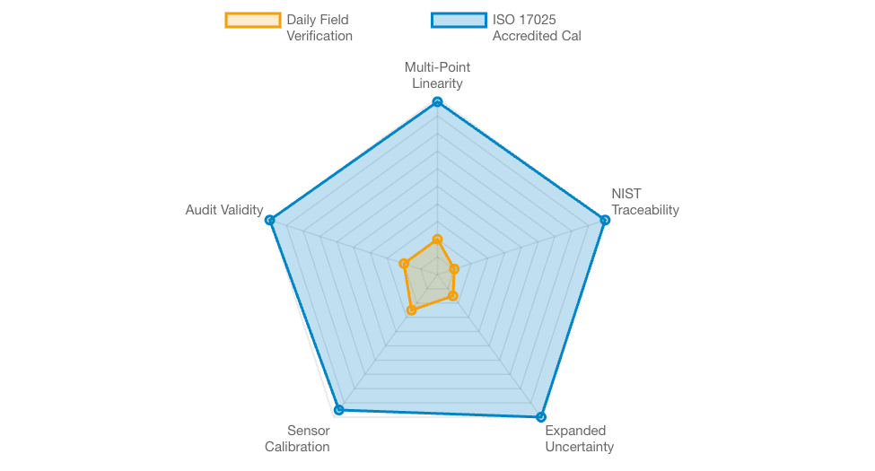
First, operators should understand the difference between a field check and formal calibration. A curve tracer’s internal auto-zero function can correct certain offset or lead effects. Likewise, a field resistor or reference module can help confirm basic operation. However, these checks do not provide a full assessment of every measurement function. For example, a simple field check may not reveal errors in voltage dividers, current measurement circuits, timing, or sensor channels. By comparison, an ISO/IEC 17025 accredited laboratory uses suitable reference standards and documented procedures. The laboratory also reports measurement results and uncertainty according to the applicable calibration scope. In addition, the calibration process can establish measurement traceability to national or international standards when the laboratory’s scope supports that claim. In the United States, this may include traceability to NIST.
What Happens When a Curve Tracer Has Measurement Errors?
Measurement errors can affect both technical decisions and financial results.
For example:
- False Pass Results: If the analyzer reports a better voltage or current result than the actual value, a degraded PV string may appear to meet its test limits. As a result, the system may produce less energy than expected over time.
- False Fail Results: If the analyzer reports worse performance than the actual value, a healthy module or string may appear defective. Therefore, technicians may spend time on unnecessary troubleshooting or warranty claims.
For this reason, regular calibration helps reduce measurement risk and supports better solar asset decisions.
2. How to Verify Curve Tracer Measurement Accuracy Before Field Testing
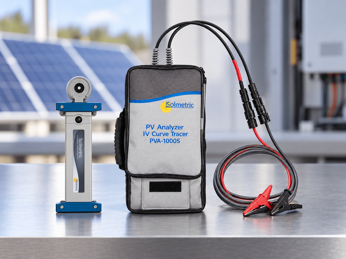
Before field testing, operators should complete basic checks on the curve tracer. The exact procedure depends on the instrument model and manufacturer instructions.
1. Inspect High-Voltage Test Leads and Connectors
First, inspect all high-voltage cables, connectors, probes, and clamps.
Look for:
- Damaged insulation
- Cracks or cuts
- Loose connectors
- Worn contact surfaces
- Corrosion
- Damaged strain relief
Next, clean suitable contact surfaces according to the manufacturer’s instructions.
Good cable condition is important because damaged or dirty connections can affect measurements and create safety concerns.
2. Power On the Analyzer and Allow It to Stabilize
Next, turn on the curve tracer and allow it to warm up.
Electronic reference circuits can change slightly as the instrument reaches its normal operating temperature. Therefore, follow the manufacturer’s recommended warm-up time.
If the manufacturer specifies a 15-minute warm-up, allow at least 15 minutes before testing.
However, do not assume that 15 minutes applies to every curve tracer. Always follow the instrument manual or calibration procedure.
3. Run the Internal Zero or Lead Compensation
After warm-up, run the analyzer’s zero or lead-compensation function when the manufacturer provides one.
This function can remove certain offset and lead effects from the measurement.
However, zero compensation does not replace calibration. It only corrects the effects that the instrument’s zero procedure can address.
4. Check Irradiance and Temperature Sensors
Next, check the irradiance and temperature sensors used by the curve tracer.
Compare the sensor readings with a suitable calibrated reference when required.
For example, verify:
- Solar irradiance
- Ambient temperature
- Module temperature
- Sensor connection
- Wireless communication
As a result, the curve tracer can use more reliable environmental data when it calculates PV performance.
5. Run a Test on a Reference Module
Finally, run an I-V sweep on a suitable reference cell, reference module, or check device.
Compare the measured values with the expected values for the reference.
Depending on the instrument, the test may include:
- Open-circuit voltage (Voc)
- Short-circuit current (Isc)
- Maximum power
- Fill factor
- I-V curve shape
If the results fall outside the expected range, stop and investigate the cause before testing a solar array.
3. Daily Field Verification vs. ISO/IEC 17025 Accredited Calibration
Daily checks and accredited calibration have different purposes.
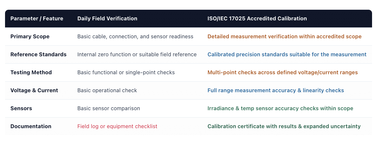
Therefore, a daily field check should support, rather than replace, periodic calibration.
For example, a technician can check the instrument before each field visit. Then, the organization can use accredited calibration at a defined interval based on equipment history and measurement risk.
Techmaster US: Your Accredited Metrology Partner
Techmaster Electronics, LLC is an ISO/IEC 17025 accredited calibration laboratory (ANAB cert AC-1736) founded in 1989. It serves the United States from five labs (four ISO/IEC 17025 accredited) in Vista, CA; Santa Clara, CA; Orlando, FL; San Antonio, TX; and Holly Springs, NC, with corporate offices in Vista, CA, and Henderson, NV.
Techmaster US provides accredited calibration services for electrical, electronic, dimensional, thermodynamic, and RF test equipment.
In addition, Techmaster US supports applicable solar and PV test equipment when the requested service falls within the laboratory’s accredited scope.
Techmaster US also offers mobile on-site calibration services for applicable equipment. Therefore, manufacturers, solar contractors, and testing teams can reduce shipping needs and limit equipment downtime when field calibration is available for the required service.
Frequently Asked Questions (FAQs)
1. What is curve tracer analyzer calibration?
Curve tracer analyzer calibration is the process of adjusting and verifying the open-circuit voltage (Voc), short-circuit current (Isc), dynamic capacitive sweep timing, and wireless sensor accuracy of a photovoltaic curve tracer against NIST-traceable standards to ensure measurement accuracy under ISO/IEC 17025 guidelines.
2. How often should a curve tracer analyzer be calibrated?
A curve tracer analyzer should be calibrated every 12 months under standard field conditions. For instruments subjected to continuous high-voltage utility commissioning, extreme ambient temperatures, or high daily sweep counts, a 6-month calibration interval is recommended to prevent reference drift.
3. Why is 4-wire Kelvin sensing essential during curve tracer calibration?
4-wire Kelvin sensing separates high-current drive leads from high-impedance voltage sense leads. This cancels out lead wire impedance and contact resistance during high-current short-circuit sweeps, enabling accurate micro-ohm and high-voltage string measurements.
4. Can field self-testing replace accredited ISO/IEC 17025 calibration?
No, field self-testing and lead zeroing only compensate for cable resistance and basic offset errors. They cannot detect internal ADC voltage divider non-linearity, current shunt thermal decay, or wireless irradiance sensor drift, which require accredited laboratory standards.
5. What parameters are tested during curve tracer analyzer calibration?
Calibration verifies high-voltage DC accuracy (up to 1500V), high-current DC linearity (up to 30A or higher), sweep timebase integration, fill factor calculation accuracy, and wireless irradiance (W/m2) and temperature sensor calibration channels.
6. Does Techmaster US offer on-site calibration for curve tracer analyzers?
Yes, Techmaster Electronics provides ISO/IEC 17025 accredited on-site calibration for curve tracers, high-voltage insulation testers, and solar photovoltaic test tools across the United States. Our mobile metrology units bring NIST-traceable standards directly to your facility or field office.
High-Voltage PV Curve Tracer Analyzer Calibration Guide
Essential metrology reference on measurement drift, I-V / P-V curve accuracy, field verification procedures, and ISO/IEC 17025 accredited calibration compliance.
CONTACT USFrequently asked questions
What is curve tracer analyzer calibration?
Curve Tracer Analyzer Calibration is the documented comparison of a curve tracer analyzer against NIST-traceable reference standards under ISO/IEC 17025. It quantifies the curve tracer analyzer’s error and measurement uncertainty and confirms it performs within tolerance, with as-found and as-left data on the certificate.
How often should a curve tracer analyzer be calibrated?
Most quality systems calibrate a curve tracer analyzer every 12 months, or sooner after repair, overload, or before critical measurements. Set your interval from the manufacturer spec and your ISO 9001 / 13485 / AS9100 program and drift history.
Is Techmaster’s curve tracer analyzer calibration ISO 17025 accredited?
Yes. Techmaster Electronics is ISO/IEC 17025:2017 accredited by ANAB (Certificate AC-1736). Every curve tracer analyzer calibration is NIST-traceable and issued with a full measurement-uncertainty budget.
What is the turnaround for curve tracer analyzer calibration?
Standard turnaround is 5 business days, with 1–2 business-day expedite available. On-site calibration removes shipping time entirely for curve tracer analyzers that can’t leave the floor.
Do you calibrate curve tracer analyzers on-site or in-lab?
Both. Techmaster runs five US labs (Vista CA, Santa Clara CA, Orlando FL, San Antonio TX, Holly Springs NC) and offers nationwide on-site curve tracer analyzer calibration to minimize downtime.

Calibration engineer at Techmaster Electronics, ISO/IEC 17025 accredited laboratory with 35+ years of metrology expertise.