
TL;DR: Most RF power sensor faults start with one event: an input above the damage level, or a connector mated badly once too often. The sensor usually still zeroes and reads, which is why the fault spreads. Check the meter reference and the connector first, expect sensing element or connector work, then a new cal factor table across frequency.
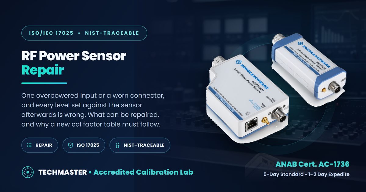
How does an RF power sensor fail?
RF power sensor repair is the restoration of a sensor’s sensing element, connector, stored correction data or interface after damage or drift, followed by a full calibration of its cal factors across frequency. The typical failure is not a dead sensor but a degraded one that still zeroes and reports plausible power.
That is what makes the failure expensive. Every level set against the sensor afterwards, amplifier gain, transmitter output, a signal generator’s own level check, carries the error forward, and nothing on the meter display contradicts it.
What should you rule out before shipping it?
The meter’s reference output, the adapter and the cable. Measure the meter’s own power reference with a second sensor, and inspect the connector with a gauge before blaming the element. A worn adapter reproduces sensor symptoms convincingly and costs far less to fix.
Connector condition deserves the first look for a second reason: a sensor with out-of-limit pin depth damages the next connector it mates with, so a bad sensor can quietly ruin a test port. The power sensor accuracy guide explains how much mismatch alone contributes to the result.
Matching symptoms to likely causes
| Symptom | Likely cause | First step |
|---|---|---|
| Readings low across frequency after an overload | Damaged sensing element | Evaluate before quoting; element replacement |
| Error that changes with frequency only | Cal factor table lost or mismatched | Confirm the stored table matches the serial number |
| Repeatability poor between connections | Connector wear or pin depth | Gauge the connector before anything else |
| Low-level readings wander after zeroing | Degrading element or zero drift | Check at the bottom of the range, not the top |
| Dropouts when the cable moves | Cable or USB interface | Substitute the cable |
| Disagrees with a second sensor at 50 MHz | Meter reference or the sensor | Cross-check both against a known sensor |
What has to happen after the repair?
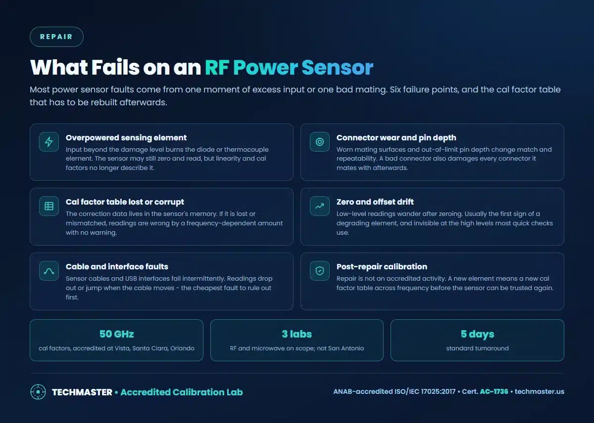
A calibration of the cal factors across the sensor’s full frequency range, plus linearity. Repair is not an accredited activity; accreditation attaches to the calibration performed afterwards. At Techmaster, cal factors to 50 GHz are accredited at Vista, Santa Clara and Orlando, not at San Antonio.
What that calibration covers: power meter and sensor calibration and RF and microwave calibration. The difference between repairing, adjusting and calibrating is set out in calibration versus verification, adjustment and repair. Other RF repairs: spectrum analyzer repair and network analyzer repair. If the sensor was in use when it failed, work through the out-of-tolerance response and check the as-found data on the certificate.
Frequently asked questions
What usually fails on an RF power sensor?
The sensing element after an overpower event, the RF connector through wear or out-of-limit pin depth, the stored cal factor table, zero and offset stability at low levels, and the sensor cable or USB interface. Most of these leave the sensor zeroing and reading as normal.
Can a burnt power sensor be repaired?
Sometimes. Damage from excess input usually means replacing the sensing element, and whether that is economical depends on the model and the availability of parts. Send the model and the symptom and we will evaluate it before quoting, so you can compare repair against replacement.
Why does a repaired power sensor need a new cal factor table?
Because the cal factors describe the sensing element, not the model. A replaced element or a reworked connector changes the frequency response, so the old table no longer applies and the sensor must be calibrated across its frequency range before use.
Where does Techmaster calibrate RF power sensors?
RF and microwave work, including power sensor cal factors to 50 GHz, is on the accredited scope at Vista CA, Santa Clara CA and Orlando FL. It is not on the San Antonio scope, so power sensors are routed to one of those three laboratories.
Techmaster Electronics is accredited by ANAB to ISO/IEC 17025:2017 under certificate AC-1736, across eight accredited calibration fields at four US laboratories, Vista CA, Santa Clara CA, Orlando FL and San Antonio TX. Ask us to confirm your specific instrument and parameter ranges against the current scope before shipping.
Send us the model list. We will come back with an itemized quote, the service level per instrument, and which items sit inside our ANAB accredited scope, usually within one business day. Request a quote.
Techmaster Electronics, LLC is an independent ISO/IEC 17025:2017 accredited calibration laboratory. We are not affiliated with, authorized by, or endorsed by any manufacturer named on this page. All product names and model designations are trademarks of their respective owners and are used here only to identify the equipment we calibrate, repair, or rent. Confirm that our accredited scope covers your instrument’s parameters and ranges before shipping, ask us and we will check it against your model list.

Khanh Nguyen is the Marketing Manager at Techmaster Electronics, a B2B marketing leader covering the test, measurement, and ISO/IEC 17025 accredited calibration industry in the United States.