

How to Use a Battery Analyzer: Setup, Operation & Best Practices

In backup power systems, electric vehicle (EV) manufacturing, and grid energy storage, accurate battery testing is essential. A battery analyzer measures key values such as DC voltage, internal resistance, impedance, and battery capacity. Therefore, learning how to use a battery analyzer correctly helps operators get reliable test results and reduce measurement errors. Over time, however, test leads can wear, probe contacts can oxidize, and internal electronic circuits can drift. As a result, battery analyzers may show small measurement errors. For this reason, operators should use the correct test method and follow a regular calibration plan. In addition, proper setup is especially important when measuring low resistance. Even a small amount of lead or contact resistance can affect milliohm readings. Therefore, 4-wire Kelvin testing, clean contacts, and correct probe pressure are key parts of reliable battery testing.
Once it is in service, the next question is the schedule; see how often to calibrate a battery analyzer.
1. Technical Principles: 4-Wire Kelvin Sensing, AC Impedance, and Lead Loss
Physics of Four-Terminal Kelvin Sensing & AC Impedance
1.1. How Four-Terminal Voltage and Impedance Sensing Works
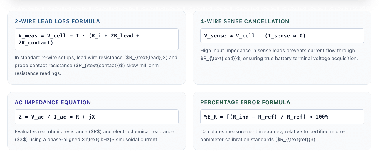
First, it is important to understand how a battery analyzer measures battery condition. A precision battery analyzer can measure open-circuit DC voltage and low internal resistance. Some models can also measure AC impedance at a set frequency, such as 1 kHz. For low-resistance measurements, the analyzer often uses a 4-wire Kelvin connection. This setup separates the current path from the voltage-sense path. In a standard two-wire setup, the test leads and contacts add resistance to the measurement. Therefore, the analyzer may measure both the battery resistance and the resistance of the test path.
A simplified relationship is: V_measured = V_cell − I × (R_internal + 2R_lead + 2R_contact)
However, a 4-wire Kelvin setup uses separate drive and sense leads. Because the sense circuit draws very little current, the voltage drop across the sense leads is very small.
As a result: V_sense ≈ V_cell
This method is especially useful when testing batteries with very low internal resistance.
1.2. How AC Impedance Is Measured
Next, some battery analyzers measure AC impedance by applying a small AC test signal to the battery.
The analyzer then measures the resulting AC voltage and current. In simple terms: Z = V_ac / I_ac = R + jX
Here, Z represents impedance, R represents the resistive part, and X represents the reactive part. However, AC impedance and DC resistance are not exactly the same measurement. The result can change with test frequency, battery chemistry, temperature, state of charge, and test method. Therefore, operators should compare results only when the same test conditions are used.
1.3. Resistance Error During Calibration
During calibration, the analyzer reading can be compared with a suitable reference standard.
The percentage resistance error can be calculated as: Resistance Error (%) = ((Indicated Resistance − Reference Resistance) / Reference Resistance) × 100
For example, if the analyzer shows a resistance higher than the reference value, the result has a positive error. Conversely, a lower reading produces a negative error.
2. Primary Hardware Degradation and Error Sources
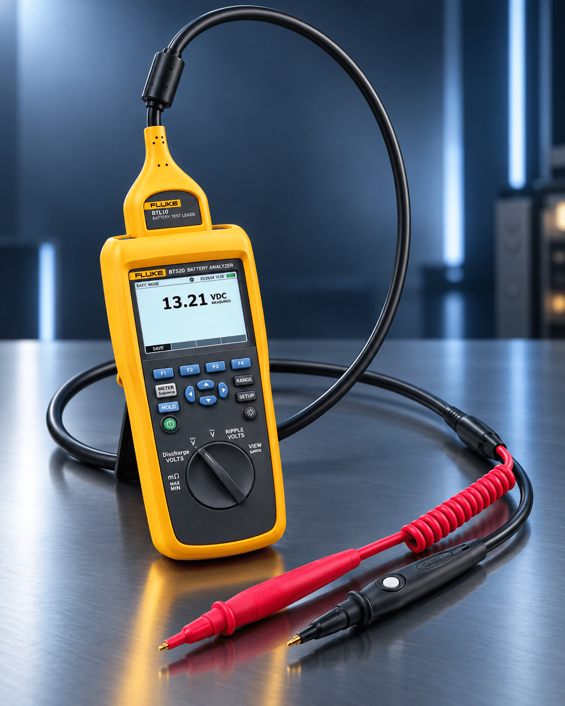
Battery analyzers can develop errors for several reasons. In particular, frequent field use and high-current testing can increase wear.
1. Test Lead Flex Fatigue
First, repeated bending can weaken the internal conductors inside probe cables. Over time, this may increase resistance or create unstable connections.
Therefore, operators should inspect cables regularly for cracks, damaged insulation, and loose connections.
2. Probe Tip Oxidation
Next, probe tips can collect dirt or develop surface oxidation. This increases contact resistance and can make low-resistance readings unstable.
For this reason, clean probe tips and battery terminals before testing.
3. Shunt Thermal Drift
High-current testing can heat the internal current shunt. As the shunt temperature changes, its resistance may also change slightly.
As a result, current measurements can drift if the instrument is not properly stabilized or calibrated.
4. Analog Circuit Drift
Internal amplifiers and reference circuits can also change with temperature and age.
Therefore, voltage and resistance measurements may develop small offset or gain errors over time.
3. Industrial Applications: Where Battery Testing Supports Reliability
 Battery analyzers are used in many industries. In each case, accurate measurements help operators identify changes in battery condition.
- Data Center UPS Maintenance: Data centers use UPS systems to provide backup power when utility power fails. Therefore, battery testing can help identify cells or battery units with abnormal voltage or resistance before they affect system performance. For VRLA and other stationary battery systems, operators should follow the applicable manufacturer instructions, site procedures, and industry standards.
- Electric Vehicle Module and Pack Testing: EV manufacturers test cells, modules, and battery packs at several stages of production. For example, battery analyzers can measure voltage, resistance, and other electrical values during cell screening and module assembly. As a result, manufacturers can identify cells or connections that differ from the required production limits.
- Grid Energy Storage Systems: Battery energy storage systems (BESS) contain many cells and modules. Because these systems operate at large scale, small differences between battery units can become important. Therefore, regular testing can help identify abnormal resistance, voltage, or performance trends.
- Telecommunications Backup Power: Telecommunications systems often use battery banks for emergency backup.
For this reason, battery analyzers can help maintenance teams check battery condition without relying only on visual inspection or system alarms.
4. How to Use a Battery Analyzer for Precision Field Testing
Follow these steps to use a battery analyzer safely and consistently.
1. Inspect the Test Leads and Kelvin Probe Tips
First, inspect the probe cables, connectors, and Kelvin tips.
Check for:
- Damaged insulation
- Loose connectors
- Worn probe tips
- Dirt or oxidation
- Broken strain relief
- Bent contact pins
If the manufacturer allows it, clean suitable metal contact surfaces with an approved cleaning method. Then allow the surface to dry before testing.
2. Power On the Battery Analyzer
Next, turn on the battery analyzer and allow it to stabilize. Many instruments need a warm-up period before accurate measurements can be made. Therefore, follow the manufacturer’s recommended warm-up time. If the manual specifies 15 minutes, allow at least 15 minutes. Otherwise, use the warm-up time stated by the manufacturer or calibration procedure.
3. Perform Zero Adjustment
After warm-up, perform the analyzer’s zero-adjust or lead-compensation procedure when required. Usually, this involves placing the probe tips together or using the supplied zero reference. The purpose is to account for small residual effects in the measurement path. However, zero adjustment is not the same as full calibration. It only helps remove certain short-term measurement effects.
4. Configure the Test Settings
Then, select the correct test mode and measurement range.
Depending on the analyzer, settings may include:
- Battery type
- Nominal voltage
- Test frequency
- Measurement range
- Resistance mode
- Warning limits
- Pass/fail limits
- Data storage settings
However, do not use a generic resistance limit for every battery.
Instead, use limits based on the battery manufacturer, equipment manufacturer, site procedure, historical data, or approved test specification.
5. Attach the Kelvin Probes Correctly
Next, place the Kelvin probes on clean battery terminals. Make sure the current and sense contacts are correctly positioned. Also, keep the probe pressure steady during the measurement. Because low-resistance testing is sensitive to contact quality, loose or uneven probe contact can cause unstable results. Therefore, do not move the probes while the analyzer is taking the reading.
6. Run the Measurement
Now start the measurement sequence. Check the displayed voltage and resistance or impedance values. If the reading is unstable, stop and inspect the connection before continuing. In addition, compare the result with previous measurements when trend data is available. For example, a sudden change from earlier readings may indicate a battery issue, a connection problem, or an instrument problem.
7. Record and Review the Results
Finally, save the measurement data according to your maintenance or quality procedure.
Record useful information such as:
- Battery ID
- Test date and time
- Voltage
- Resistance or impedance
- Temperature
- Analyzer ID
- Operator
- Test location
As a result, trend data can help maintenance teams identify gradual changes over time.
Frequently Asked Questions (FAQs)
1. How to use a battery analyzer to check internal resistance accurately?
To check internal resistance accurately, clean the battery terminals, connect 4-wire Kelvin probes directly to the cell posts, and perform a zero-adjust procedure before testing. Ensure firm contact on both inner and outer probe pins to eliminate lead resistance errors.
2. What is the difference between AC impedance and DC resistance testing in battery analyzers?
AC impedance testing applies a 1 kHz low-amplitude AC current to measure internal electrochemical opposition (Z), making it ideal for rapid field testing. DC resistance testing applies a stepped load pulse to measure total ohmic resistance plus polarization effects, reflecting true load capability under high-current discharge.
3. How often should a commercial battery analyzer be calibrated?
A commercial battery analyzer should be calibrated every 12 months under normal field testing conditions. Units used continuously in high-volume production line sorting or extreme environmental conditions should be calibrated every 6 months to ensure measurement accuracy.
4. Why does a battery analyzer require 4-wire Kelvin probes?
4-wire Kelvin probes separate current drive lines from high-impedance voltage sense lines. This configuration cancels out test lead resistance and contact resistance, enabling accurate micro-ohm measurement of low-impedance secondary cells.
5. What causes unstable internal resistance readings during battery testing?
Unstable readings are caused by dirty or oxidized battery terminals, worn probe pins, loose cable connectors, electromagnetic interference from nearby operating equipment, or improper probe pressure. Cleaning contacts and performing probe zeroing resolves most stability issues.
6. Can Techmaster US perform on-site calibration for battery analyzers and UPS test equipment?
Yes, Techmaster Electronics provides ISO/IEC 17025 accredited on-site calibration for battery analyzers, multimeters, and electrical power test tools across the United States. Our field metrologists bring NIST-traceable standards directly to your facility to minimize downtime.
How to Use a Battery Analyzer: Setup, Operation & Best Practices
Comprehensive technical reference for 4-wire Kelvin sensing, 1 kHz AC impedance testing, open-circuit DC voltage verification, state-of-health (SOH) trending, and ISO/IEC 17025 metrology compliance.
CONTACT USFrequently asked questions
What is battery analyzer calibration?
Battery Analyzer Calibration is the documented comparison of a battery analyzer against NIST-traceable reference standards under ISO/IEC 17025. It quantifies the battery analyzer’s error and measurement uncertainty and confirms it performs within tolerance, with as-found and as-left data on the certificate.
How often should a battery analyzer be calibrated?
Most quality systems calibrate a battery analyzer every 12 months, or sooner after repair, overload, or before critical measurements. Set your interval from the manufacturer spec and your ISO 9001 / 13485 / AS9100 program and drift history.
Is Techmaster’s battery analyzer calibration ISO 17025 accredited?
Yes. Techmaster Electronics is ISO/IEC 17025:2017 accredited by ANAB (Certificate AC-1736). Every battery analyzer calibration is NIST-traceable and issued with a full measurement-uncertainty budget.
What is the turnaround for battery analyzer calibration?
Standard turnaround is 5 business days, with 1–2 business-day expedite available. On-site calibration removes shipping time entirely for battery analyzers that can’t leave the floor.
Do you calibrate battery analyzers on-site or in-lab?
Both. Techmaster runs five US labs (Vista CA, Santa Clara CA, Orlando FL, San Antonio TX, Holly Springs NC) and offers nationwide on-site battery analyzer calibration to minimize downtime.
References & industry standards
- ISO/IEC 17025 testing & calibration laboratory requirements
- NIST calibration services and measurement traceability
- A2LA / ANAB accreditation for calibration laboratories
External standards bodies. Techmaster Electronics is an ISO/IEC 17025-accredited, NIST-traceable calibration laboratory.

Khanh Nguyen is the Marketing Manager at Techmaster Electronics, a B2B marketing leader covering the test, measurement, and ISO/IEC 17025 accredited calibration industry in the United States.