

How to Use an Ultrasonic Thickness Gauge: Setup, Operation & Best Practices
Non-destructive testing (NDT) teams, quality engineers, and maintenance staff use ultrasonic thickness gauges to check material thickness without cutting or damaging the part. Knowing how to use an ultrasonic thickness gauge correctly helps detect corrosion, wall loss, and material changes before they become serious problems. However, incorrect probe placement, wrong sound velocity settings, or poor surface contact can cause inaccurate readings. Therefore, users should follow a clear setup and measurement process to get reliable results.
1. Technical Principles: Pulse-Echo, Sound Velocity, and V-Path Correction
1.1. How Ultrasonic Thickness Measurement Works
An ultrasonic thickness gauge measures material thickness by sending high-frequency sound waves into the test material. Most gauges use frequencies between 1 MHz and 10 MHz.
Inside the transducer, a piezoelectric crystal changes an electrical pulse into an ultrasonic wave. The wave then travels through the material until it reaches the back wall. After that, the wave reflects back to the transducer.
The gauge measures the time needed for the sound wave to travel through the material and return. It then uses the material sound velocity to calculate the thickness.
Plain-text formula:
Thickness = Sound Velocity × Travel Time / 2
Here:
- Thickness is the material wall thickness.
- Sound Velocity is the speed of sound in the test material.
- Travel Time is the measured round-trip time of the ultrasonic pulse.f$
1.2. Material Sound Velocity
Sound velocity changes from one material to another. Therefore, setting the correct velocity is one of the most important steps when using an ultrasonic thickness gauge.
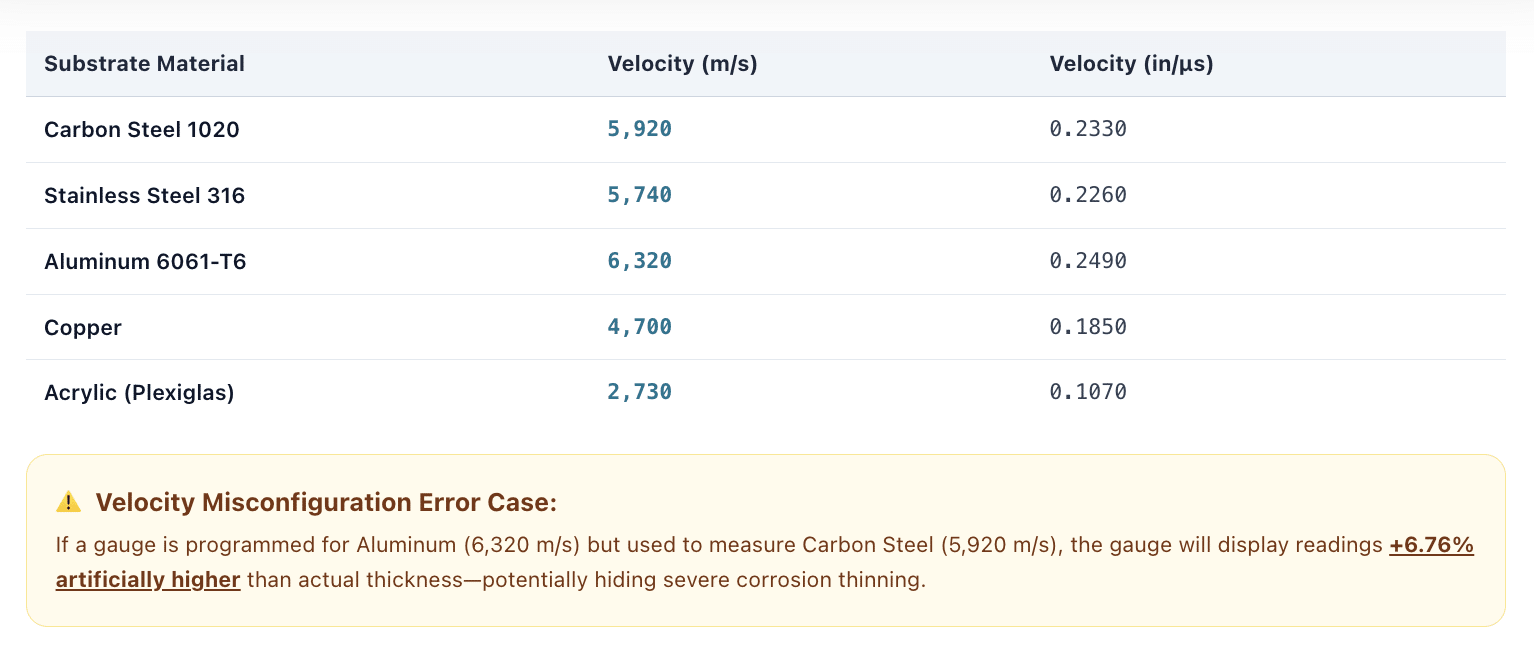
Material Substrate Acoustic Velocity Comparison
Acoustic velocity varies dramatically depending on material density and elastic modulus. Because thickness is directly proportional to sound velocity, failing to configure the exact material velocity results in proportional measurement error across all readings.
Bạn cần hiệu chuẩn thiết bị chuyên sâu và lấy chứng chỉ đạt chuẩn?
Liên hệ với kỹ sư Techmaster USThese values are typical reference values. In practice, the actual velocity can vary with alloy, temperature, material condition, and microstructure. For this reason, users should verify the velocity with a known reference standard whenever possible.
1.3. Dual-Element Transducers and V-Path Correction
Dual-element transducers use separate transmitting and receiving elements. These elements usually sit at a small angle and point toward each other.
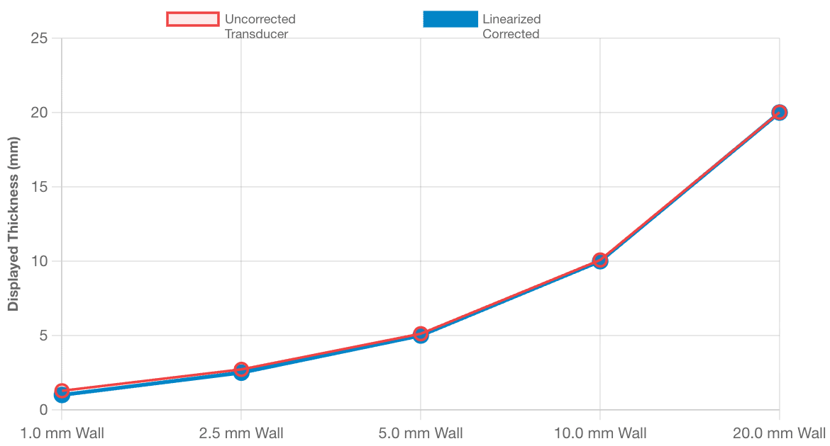
As a result, the ultrasonic wave follows a V-shaped path through the material. This path can affect the measured travel time, especially when measuring thin sections.
Modern ultrasonic thickness gauges can apply V-path correction through internal software. Therefore, the gauge can improve measurement accuracy across a wider thickness range.
2. Industrial Applications: NDT and Asset Inspection
Ultrasonic thickness gauges support many inspection and quality control tasks. For example, inspectors can measure wall thickness without removing the part from service in many applications.
Common uses include:
- Oil and Gas Pipeline Inspection: Inspectors measure remaining wall thickness to find corrosion, pitting, erosion, and other forms of wall loss.
- Pressure Vessels and Chemical Equipment: Maintenance teams check vessel walls and tanks for thinning during planned inspections.
- Aerospace and Automotive Components: Technicians measure metal sections, cast parts, and other components to verify thickness requirements.
- Marine and Offshore Structures: Inspectors check ship hulls, tanks, and steel structures for corrosion and material loss.
In addition, ultrasonic thickness gauges can support routine maintenance programs. By recording thickness readings over time, teams can track wall loss and identify areas that need closer inspection.
3. How to Set Up and Use an Ultrasonic Thickness Gauge
Follow these steps to improve measurement consistency during field or laboratory testing.
1. Clean the Test Surface
First, clean the test area before taking a measurement. Remove loose rust, scale, dirt, and loose coatings.
Use a wire brush, scraper, or other suitable surface preparation tool. However, avoid removing too much material from the test area.
A clean and smooth surface helps the transducer make better contact with the material.
2. Inspect the Transducer
Next, check the transducer before use.
Look for scratches, wear, cracks, or other damage on the probe face. Also, inspect the cable and connectors for damage or loose connections.
If the transducer shows signs of wear, replace it or follow the manufacturer’s inspection procedure before continuing.
3. Perform Probe Zeroing
Then, perform the probe zero procedure according to the gauge manufacturer’s instructions.
Apply a small amount of couplant to the gauge’s reference block or zeroing surface. Press the transducer firmly against the surface and run the zero function.
Probe zeroing helps the gauge account for the delay caused by the transducer and its protective layer.
However, probe zeroing does not replace a full calibration.
4. Set the Correct Material Velocity
After that, set the sound velocity for the material being tested.
You can select a material from the gauge’s built-in menu or enter a known velocity manually.
For the best results, verify the setting against a reference block made from the same or a closely matched material.
5. Apply Ultrasonic Couplant
Next, apply a small and even amount of ultrasonic couplant to the test surface.
The couplant fills tiny air gaps between the transducer and the material. As a result, ultrasonic energy can enter the material more efficiently.
Common couplants include gels and other liquids designed for ultrasonic testing. Always choose a couplant that suits the material, temperature, and test conditions.
6. Position the Transducer and Take the Reading
Finally, place the transducer firmly on the test surface.
Keep the probe as stable and perpendicular to the surface as possible. For curved surfaces, make sure the probe has enough contact with the material.
Wait for the reading to stabilize. Then, record the thickness value and any relevant measurement information.
For critical inspections, take several readings around the same area. If the values vary significantly, check the surface, probe position, couplant, and gauge settings before accepting the result.
4. Best Practices for Reliable Thickness Measurements
To improve measurement quality, follow these basic practices:
- Use the correct transducer for the thickness and material range.
- Keep the probe face clean and free from damage.
- Use enough couplant to create good acoustic contact.
- Verify sound velocity before critical measurements.
- Take multiple readings when the surface is rough or curved.
- Avoid measuring over loose scale or unstable coatings unless the gauge and method support it.
- Record the material, probe type, velocity setting, temperature, and measurement location when required.
- Compare results with previous inspection data when monitoring wall loss over time.
- Follow the manufacturer’s operating instructions and calibration requirements.
Most importantly, use a calibrated gauge for measurements that support quality, safety, or compliance decisions.
Frequently Asked Questions (FAQs)
1. How to use a ultrasonic thickness gauge on painted or coated surfaces?
To use an ultrasonic thickness gauge on painted or coated surfaces, select an echo-to-echo (thru-paint) measurement mode with a multi-echo dual transducer. This mode sends multiple back-wall echoes through the material, calculating substrate wall thickness while mathematically ignoring the surface paint coating layer.
2. What is the purpose of ultrasonic couplant gel during thickness testing?
Ultrasonic couplant gel eliminates microscopic air gaps between the transducer face and the material surface. Because high-frequency sound waves travel poorly through air, couplant creates a smooth acoustic bridge that allows sound energy to transfer efficiently into the test substrate.
3. How often should an ultrasonic thickness gauge be calibrated?
An ultrasonic thickness gauge should undergo ISO/IEC 17025 accredited calibration every 12 months under standard operating conditions. Instruments deployed in severe field environments, extreme thermal conditions, or continuous daily production line inspections should be calibrated every 6 months.
4. What causes inaccurate thickness readings on curved pipe surfaces?
Inaccurate thickness readings on curved pipes stem from poor transducer contact alignment and V-path acoustic distortion. To achieve accurate measurements, align the dual-element transducer’s internal sound-barrier line perpendicular to the long axis of the pipe.
5. Why does substrate temperature affect ultrasonic thickness gauge readings?
Substrate temperature affects ultrasonic thickness gauge readings because thermal expansion alters material density and slows down sound propagation. High temperatures decrease acoustic velocity, causing uncompensated thickness gauges to display artificially thick wall measurements.
How to Use an Ultrasonic Thickness Gauge
Master setup, acoustic velocity calibration, probe zeroing, V-path error correction, and surface temperature compensation to prevent catastrophic asset wall failures and guarantee precise quality control.
CONTACT USReferences & industry standards
- ISO/IEC 17025 testing & calibration laboratory requirements
- NIST calibration services and measurement traceability
- A2LA / ANAB accreditation for calibration laboratories
External standards bodies. Techmaster Electronics is an ISO/IEC 17025-accredited, NIST-traceable calibration laboratory.
Frequently asked questions
What is ultrasonic thickness gauge calibration?
Ultrasonic Thickness Gauge Calibration is the documented comparison of a ultrasonic thickness gauge against NIST-traceable reference standards under ISO/IEC 17025. It quantifies the ultrasonic thickness gauge’s error and measurement uncertainty and confirms it performs within tolerance, with as-found and as-left data on the certificate.
How often should a ultrasonic thickness gauge be calibrated?
Most quality systems calibrate a ultrasonic thickness gauge every 12 months, or sooner after repair, overload, or before critical measurements. Set your interval from the manufacturer spec and your ISO 9001 / 13485 / AS9100 program and drift history.
Is Techmaster’s ultrasonic thickness gauge calibration ISO 17025 accredited?
Yes. Techmaster Electronics is ISO/IEC 17025:2017 accredited by ANAB (Certificate AC-1736). Every ultrasonic thickness gauge calibration is NIST-traceable and issued with a full measurement-uncertainty budget.
What is the turnaround for ultrasonic thickness gauge calibration?
Standard turnaround is 5 business days, with 1–2 business-day expedite available. On-site calibration removes shipping time entirely for ultrasonic thickness gauges that can’t leave the floor.
Do you calibrate ultrasonic thickness gauges on-site or in-lab?
Both. Techmaster runs five US labs (Vista CA, Santa Clara CA, Orlando FL, San Antonio TX, Holly Springs NC) and offers nationwide on-site ultrasonic thickness gauge calibration to minimize downtime.

Calibration engineer at Techmaster Electronics, ISO/IEC 17025 accredited laboratory with 35+ years of metrology expertise.